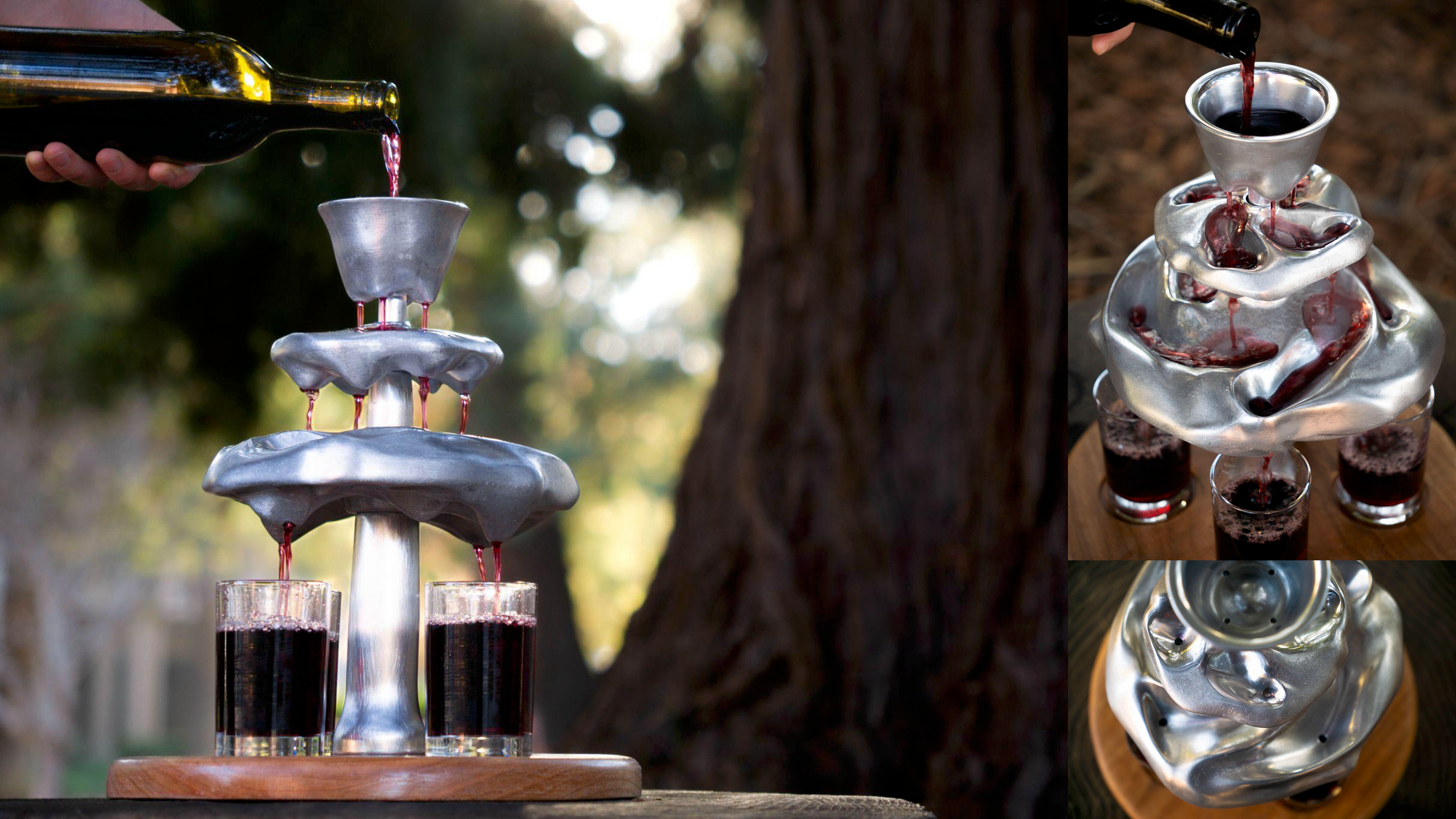
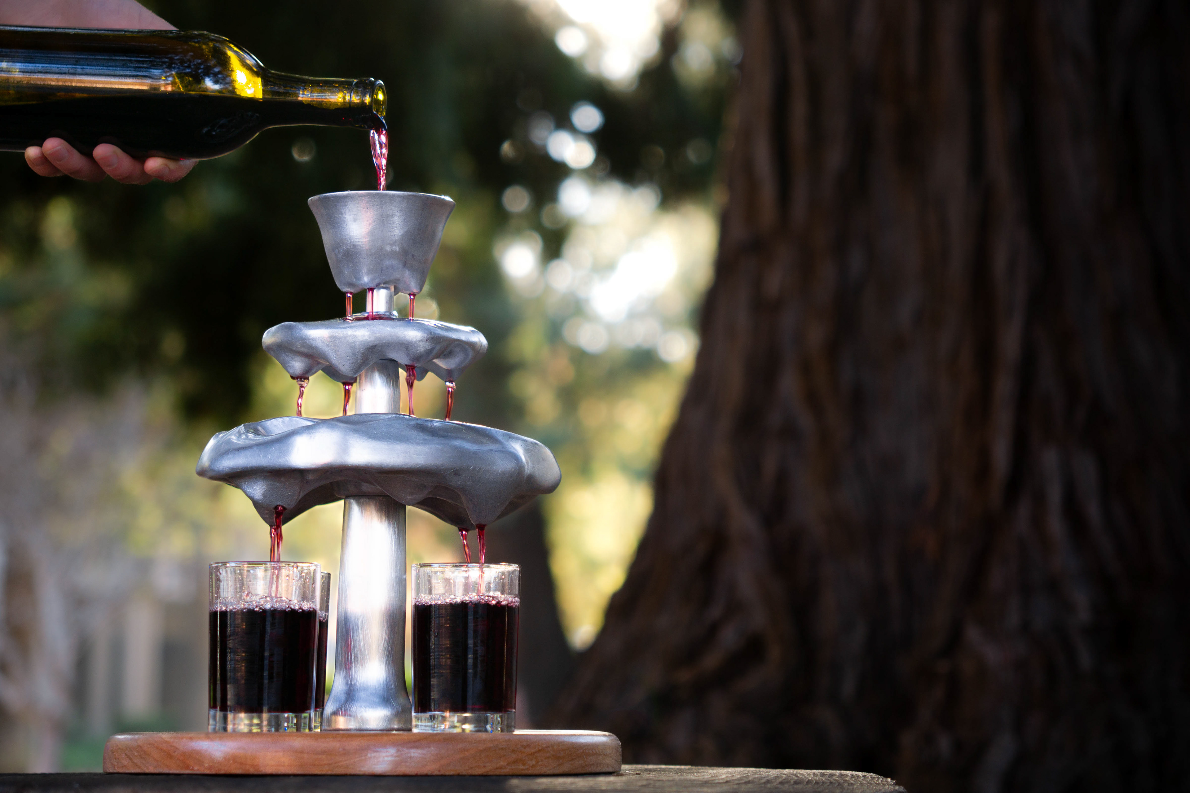
Redwine Tree
This project was created for ME 103: Design and Manufacturing at Stanford University
Skills
Product Design
Metals Fabrication
Prototyping
Timeline
Sep - Dec 2025
10 weeks
Overview
Growing up having paintball wars and stick fights in the redwoods in my backyard, I've always felt a strong connection to these mystical trees. Being raised Catholic and participating in holy communion as a child, wine has always held a spiritual significance to me. Redwine tree combines these two childhood influences while transforming the act of pouring drinks into a shared experience.
The top cup and the two plates with channels were sand cast using A356 aluminum and post-processed on the mill. The center rod was turned from aluminum 6061 round stock. The wooden base is cherry.
Sketches
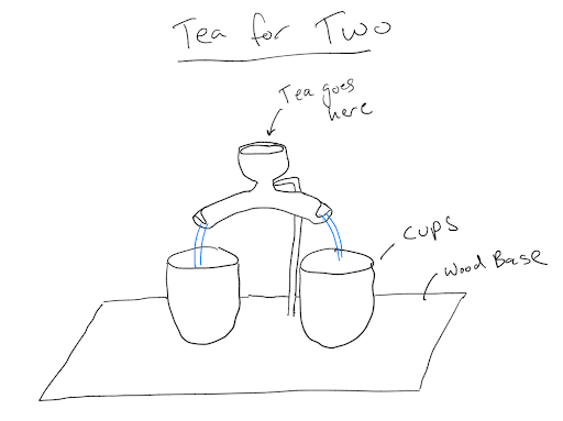
Sketch #1: a diverter, which pours into two tea cups.
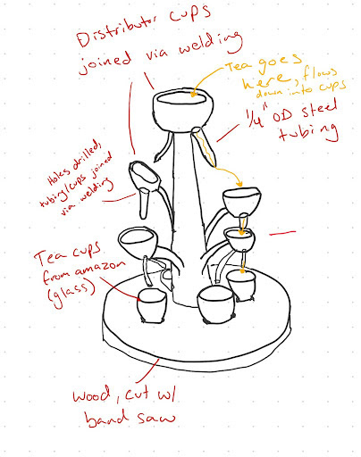
Sketch #2: exploring tree-like shapes.
Due to aluminum's high thermal conductivity, I decided early on to use it for wine instead of tea, since hot tea would cool down too much before reaching the cups.
Rapid Prototyping
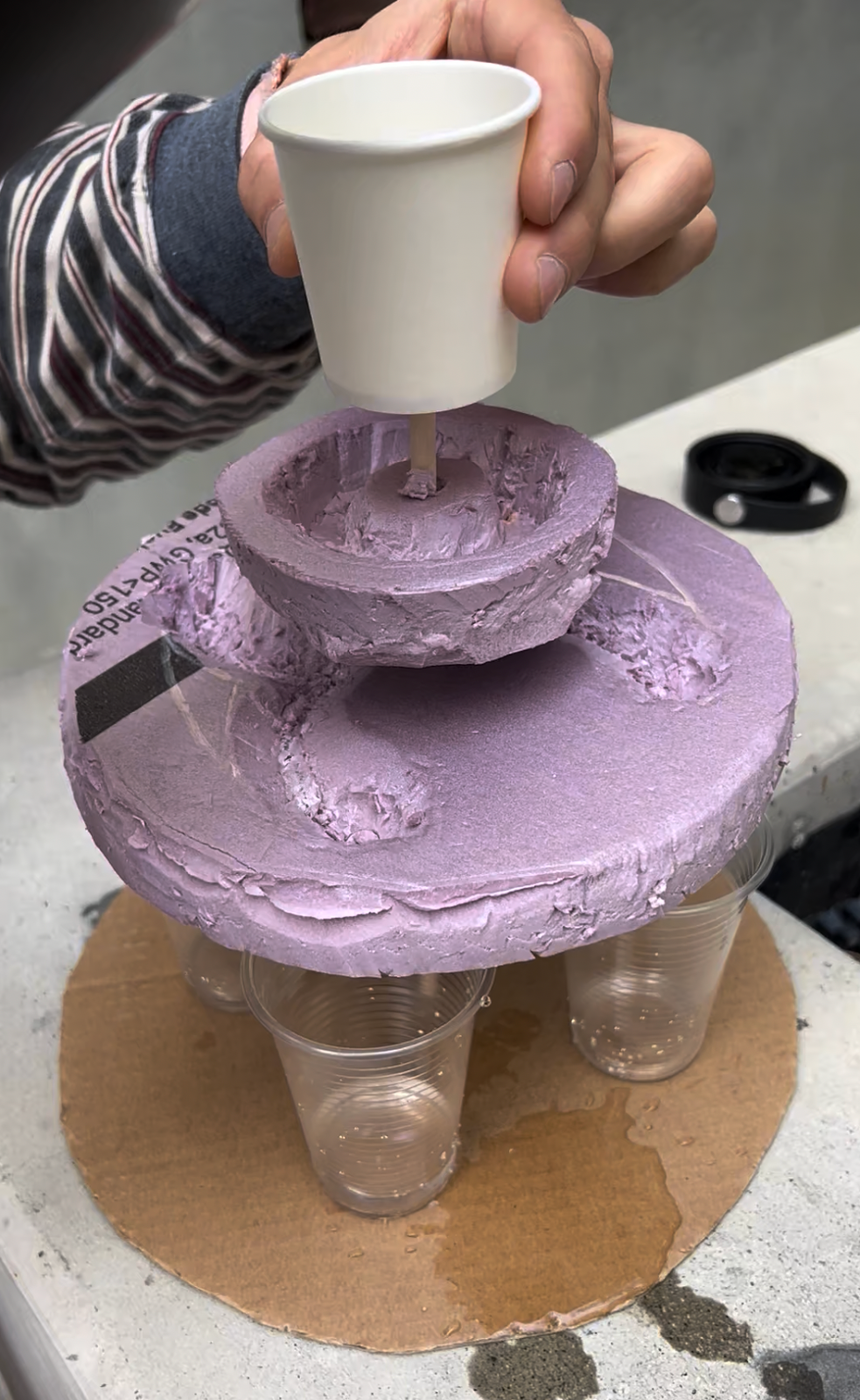
I made three prototypes in order to answer the question: will it pour evenly and not overflow?
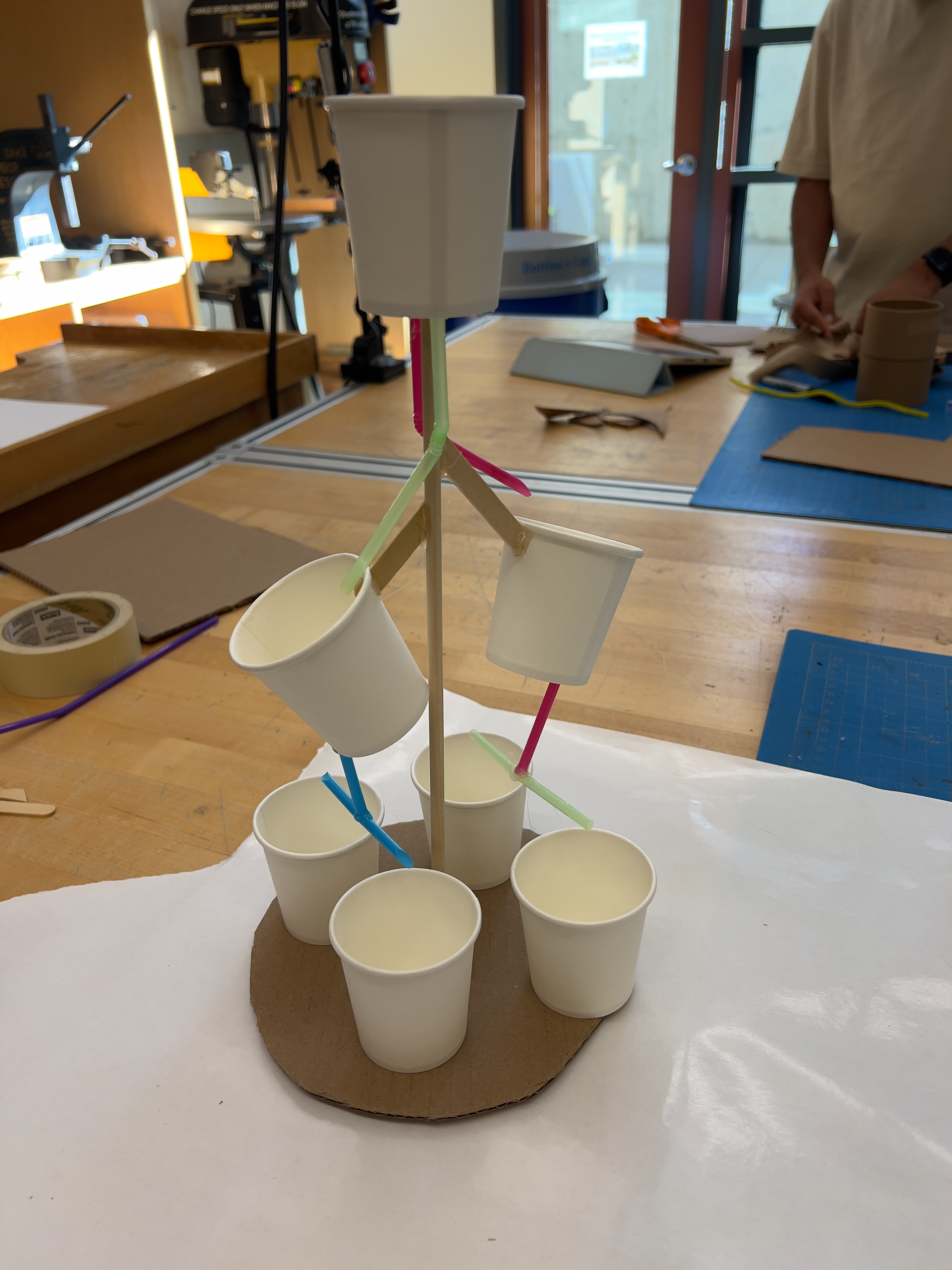
Prototype #1 made from paper cups, straws, sticks, and hot glue.
Prototype #2 features a top cup with two plates that divert the liquid stream.
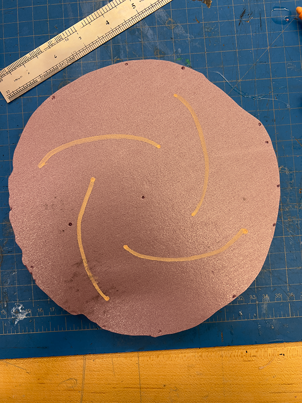
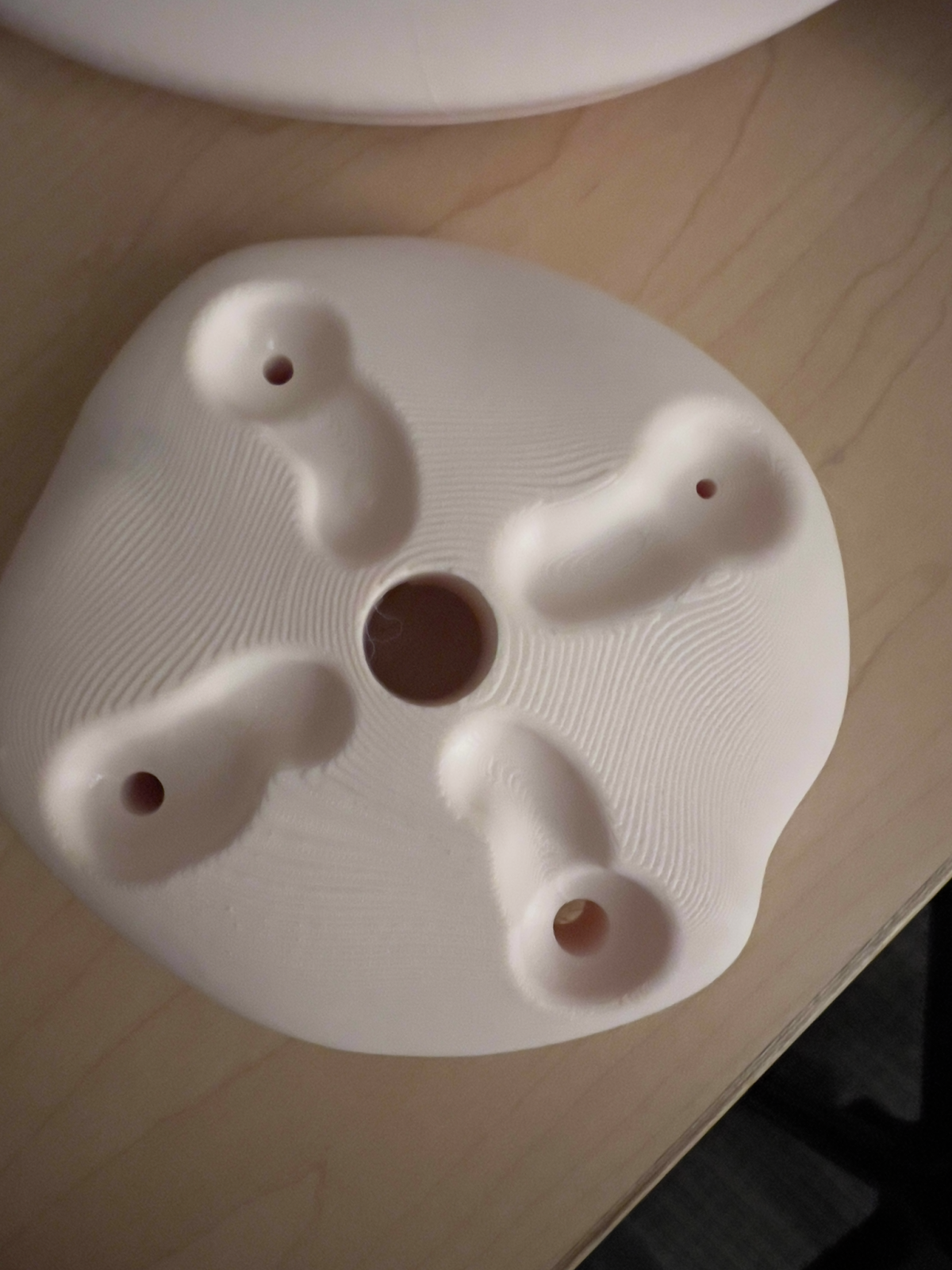
Channel cut-outs for prototype #3.
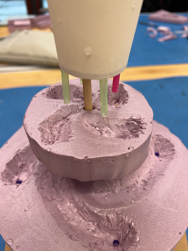
Prototype #3: top cup divides into four isolated streams.
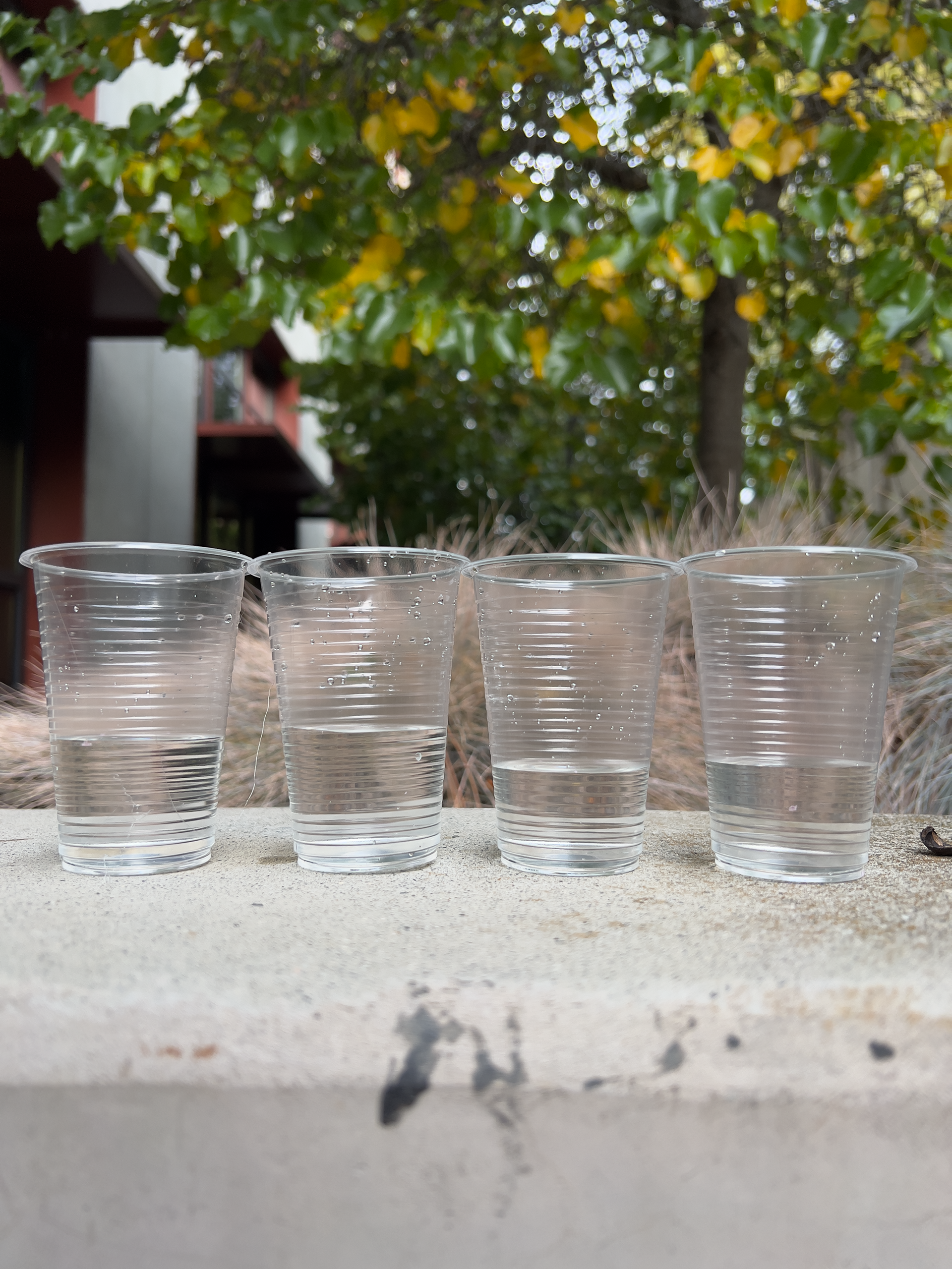
Prototype #3 result (not perfect due to inaccuracy of hot gluing the straws into the cup)
Key takeaways:
1. In order to get four even pours, the four holes in the top cup will need to be the same size and at the same height. After that, the channel geometry doesn't matter as long as the streams are isolated and they don't overflow.
2. Simpler is better. I was able to reduce the total number of fabricated parts from 19 down to 5.
CAD Models and Testing
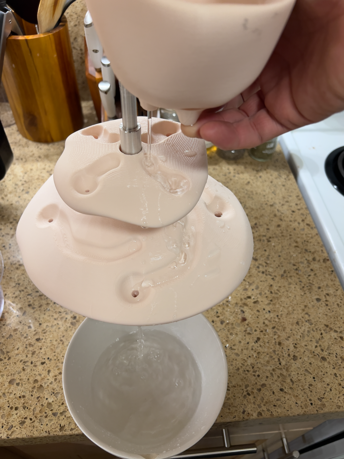
In order to be completely sure that my project would function correctly before sand casting it, I had to test the liquid pour on the exact design geometry. The best way to test this was by 3D printing it.
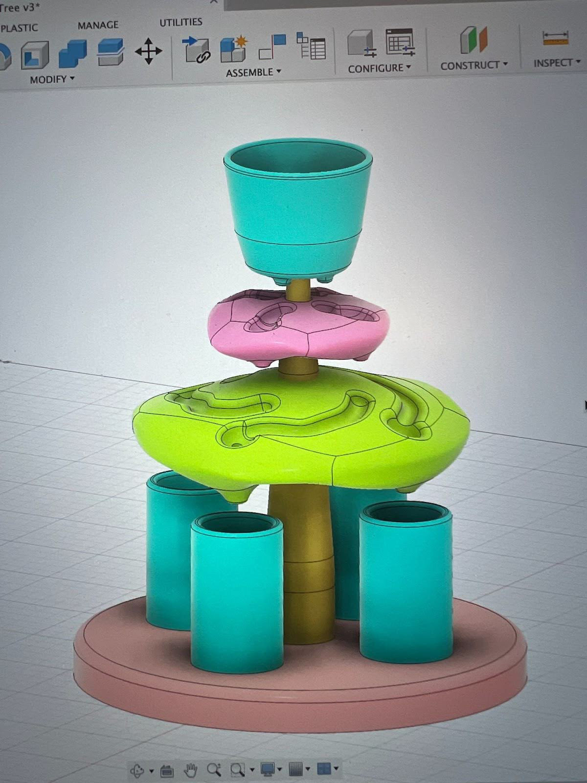
Initial CAD model
Testing four different hole sizes
Testing the flow down individual streams
Key takeaways:
1. The channels were too small, causing the water to over flow.
2. Ratios were imbalanced. Visually, it was too top heavy and I was unhappy with the overall design.
Revised CAD model
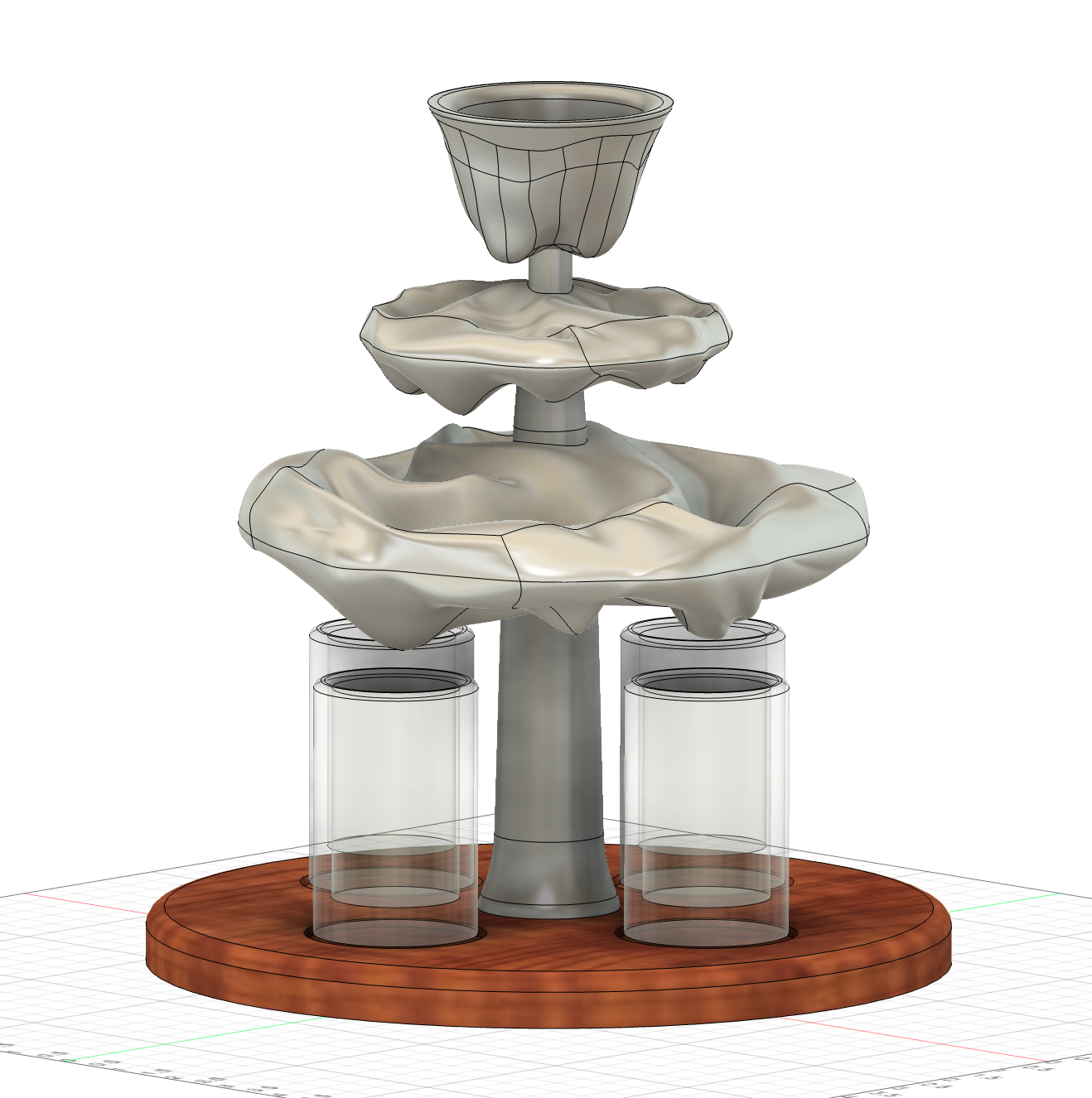
Final CAD model
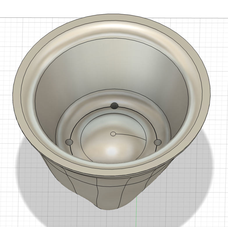
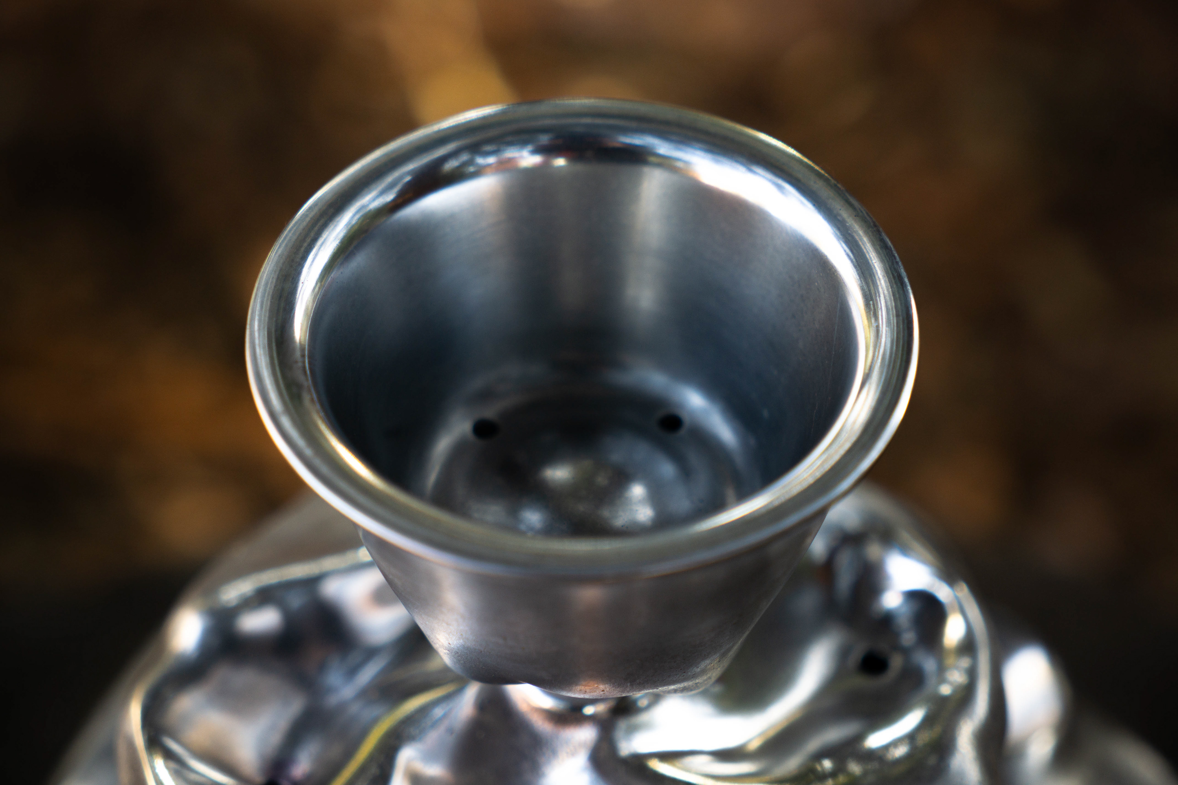
Top cup
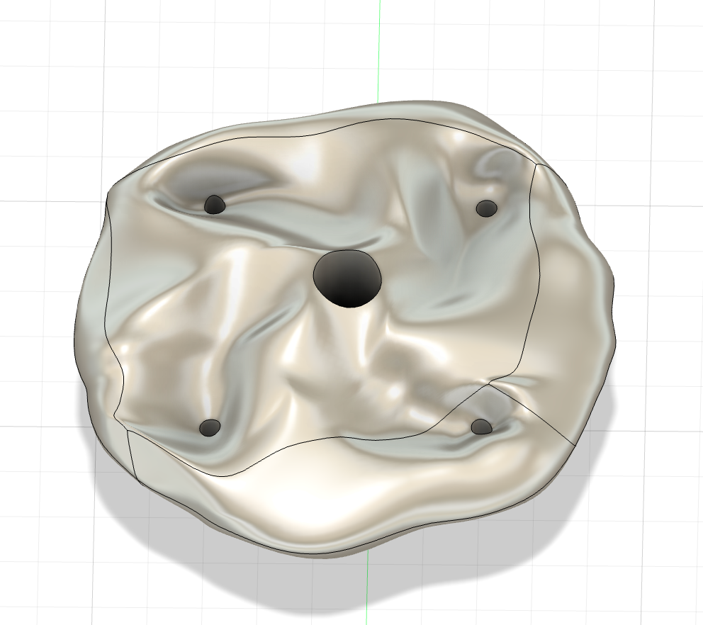
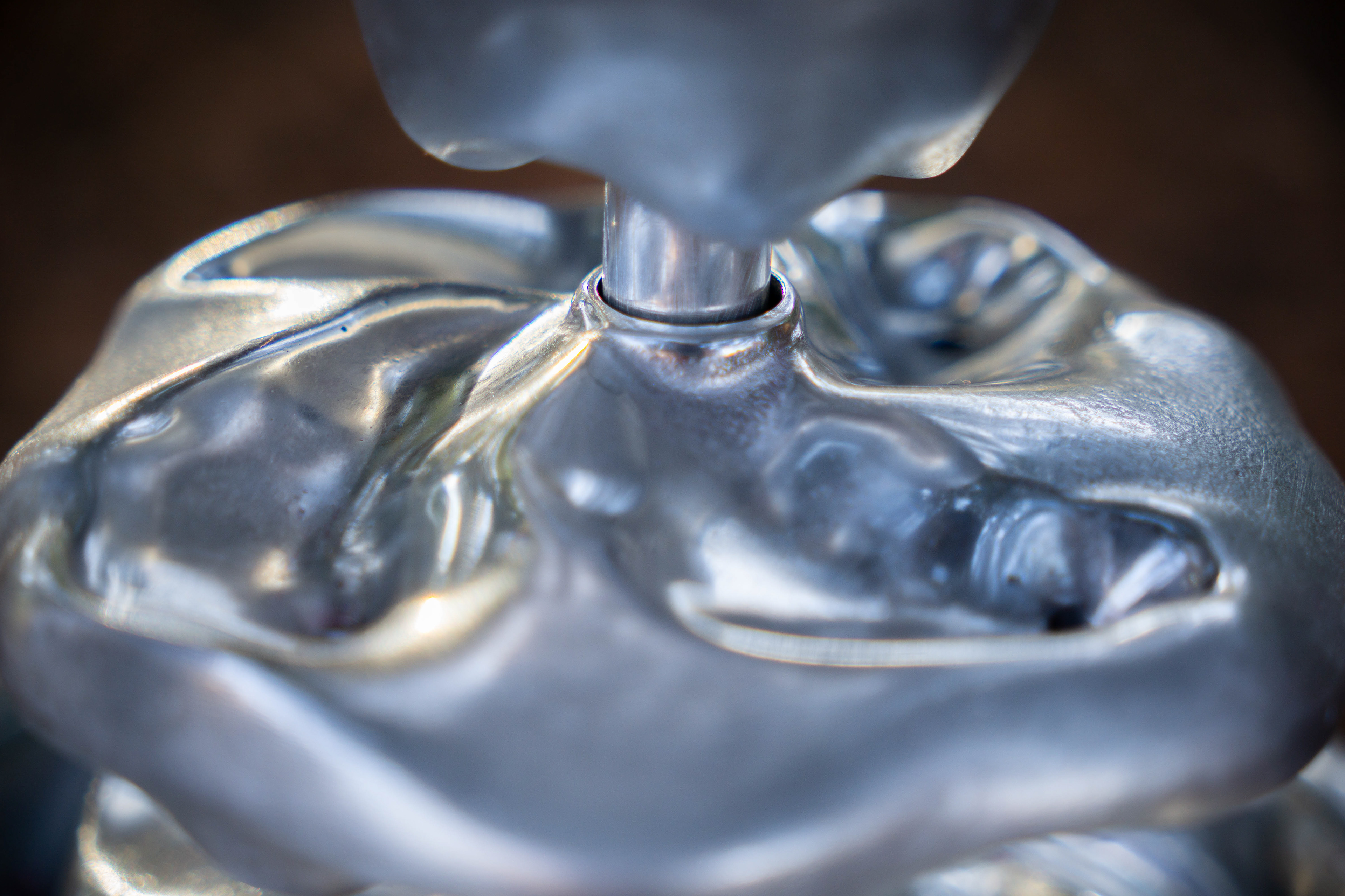
Top plate
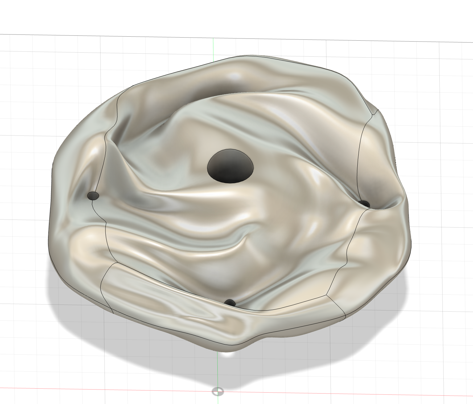
Bottom plate
Operations Sequence and Bill of Materials
Fabrication
Center rod
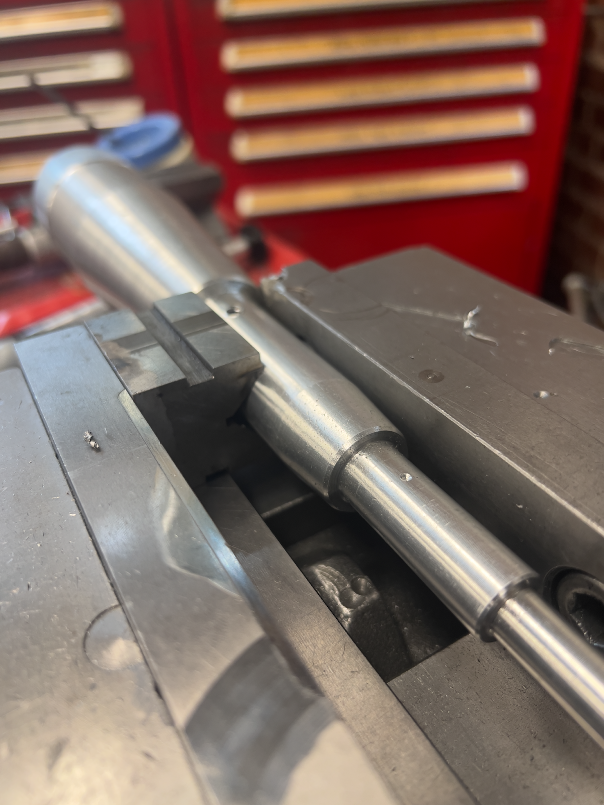
Starting with a 2" diameter x 12" long aluminum 6061 round stock, I turned down the diameters to size. I then drilled and tapped holes for mounting the rod to the wooden base, and for inserting the ball detents which align my components. I then added a radius at the bottom, inspired by the curvature of a redwood tree I saw while riding my bike on campus.
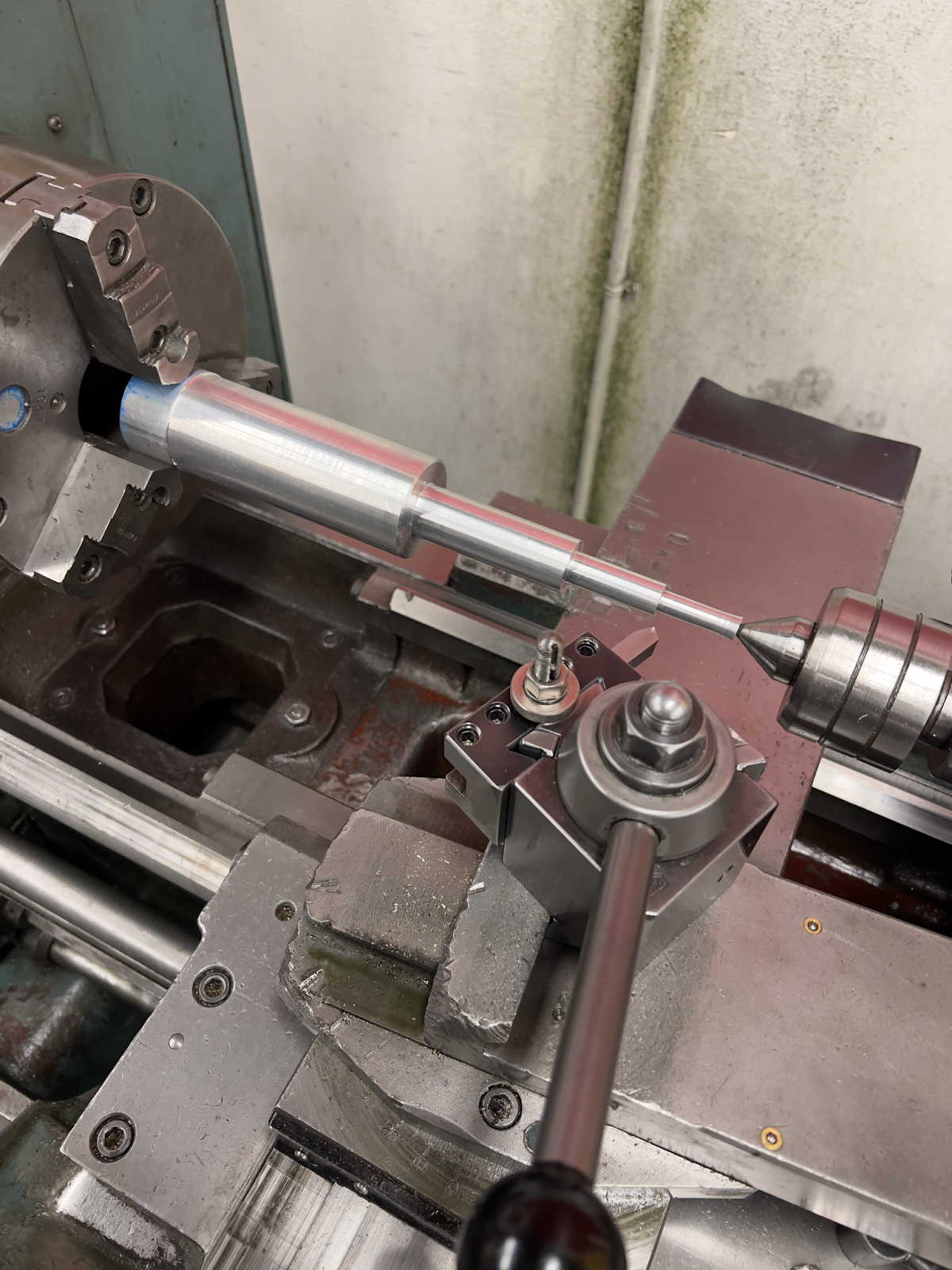
Turning down to diameter.
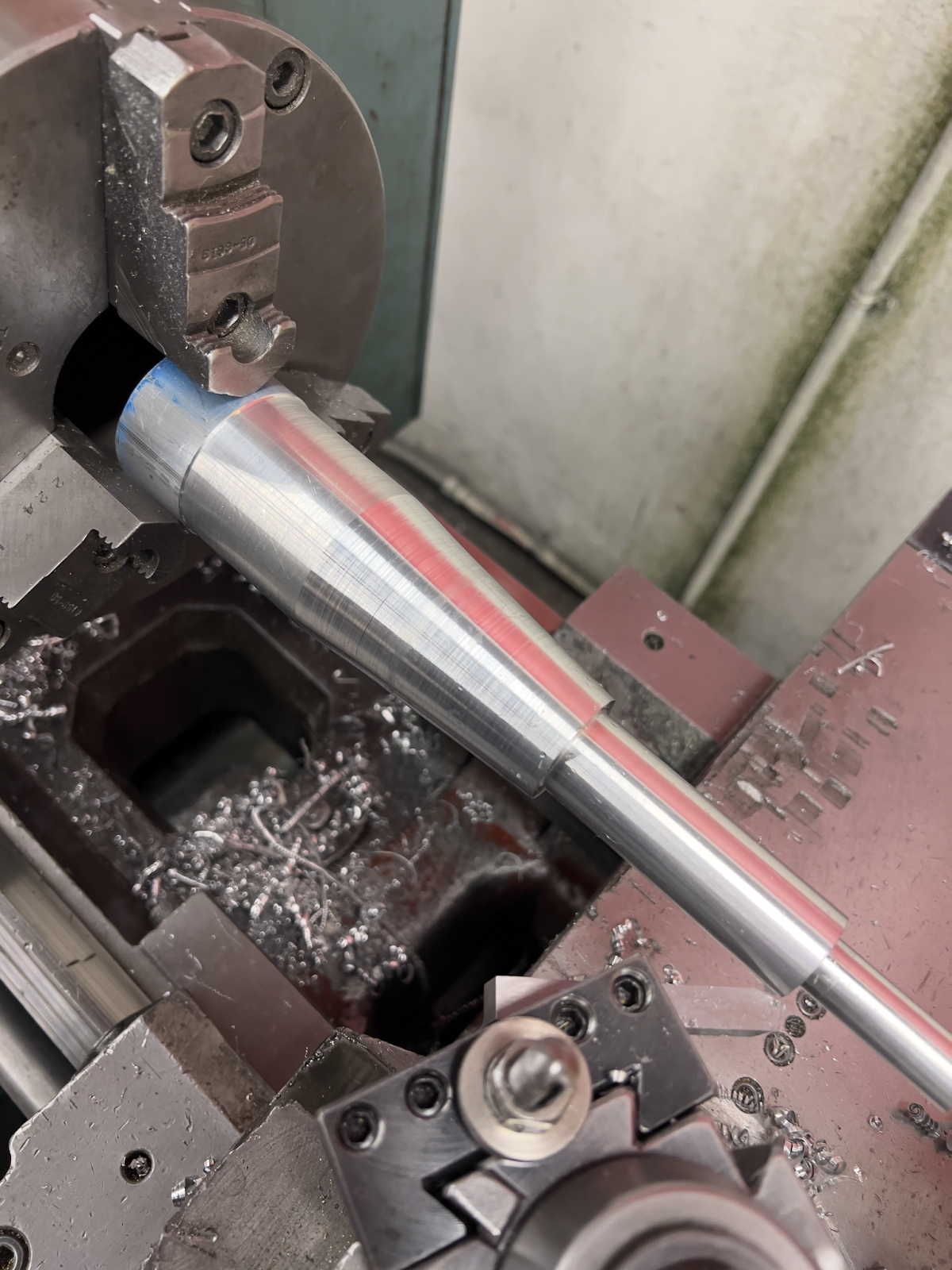
Adding tapers and chamfering corners.
Drilling holes for ball detents on the mill.
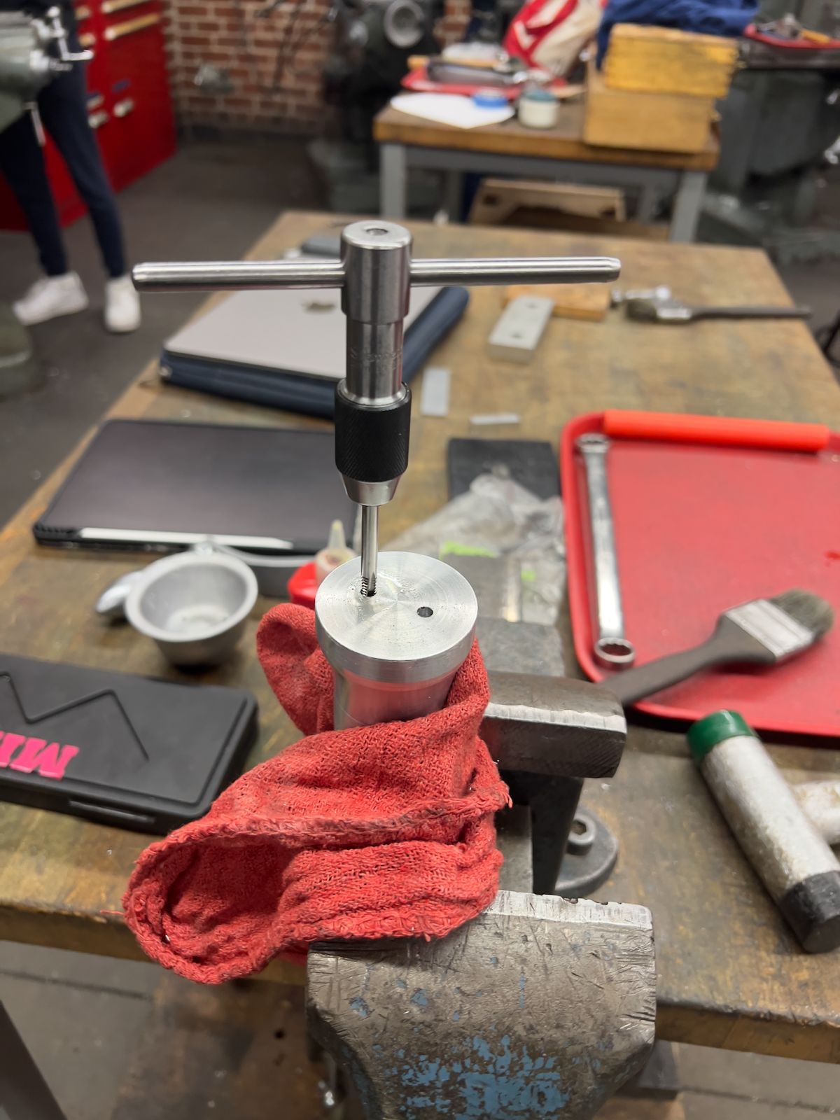
Tapping the holes.
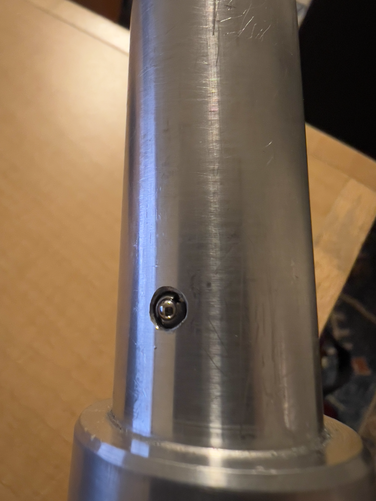
Installing ball detents.
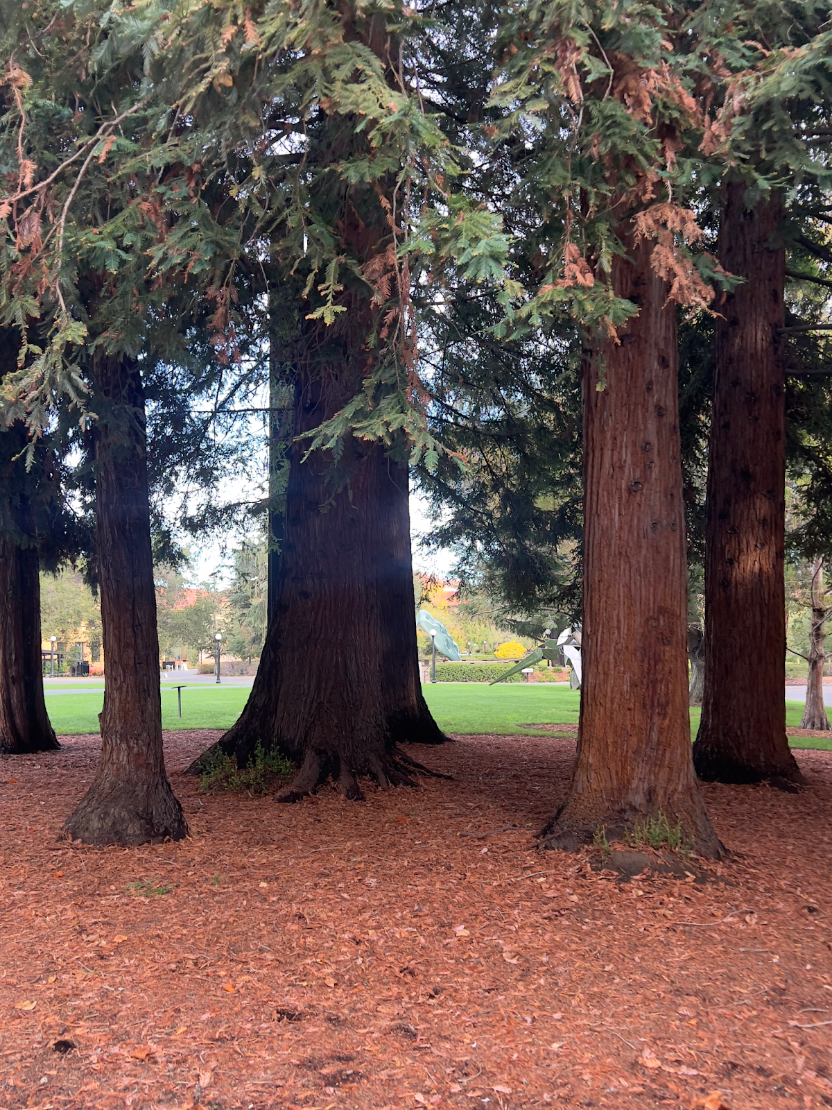
Using inspiration from the curvature of this redwood tree trunk on campus.
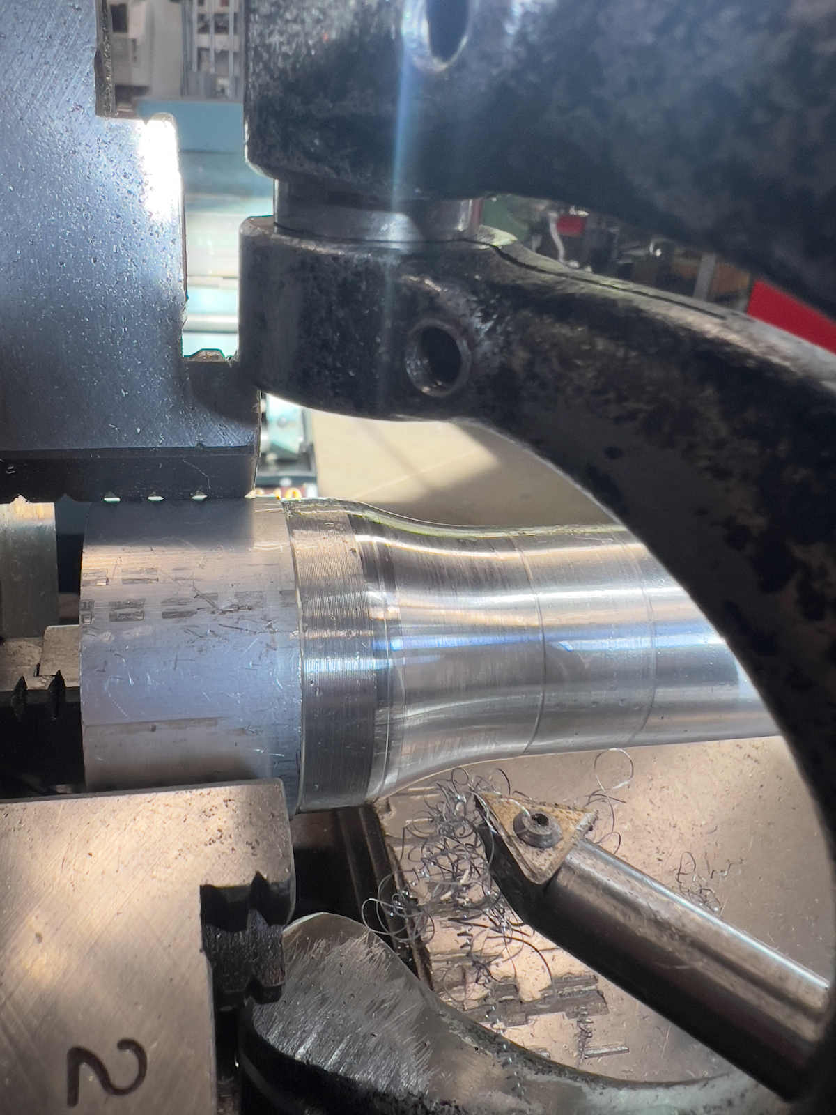
Using radius cutter to make the rod more tree trunk-like.
Sand Casting
I began by 3D printing each pattern using PLA, with added features for edge finding on the mill. I then sanded the patterns, applied shellac, and made pattern boards out of 3/4" plywood. Below are the results of ramming up and pouring with aluminum 356A.
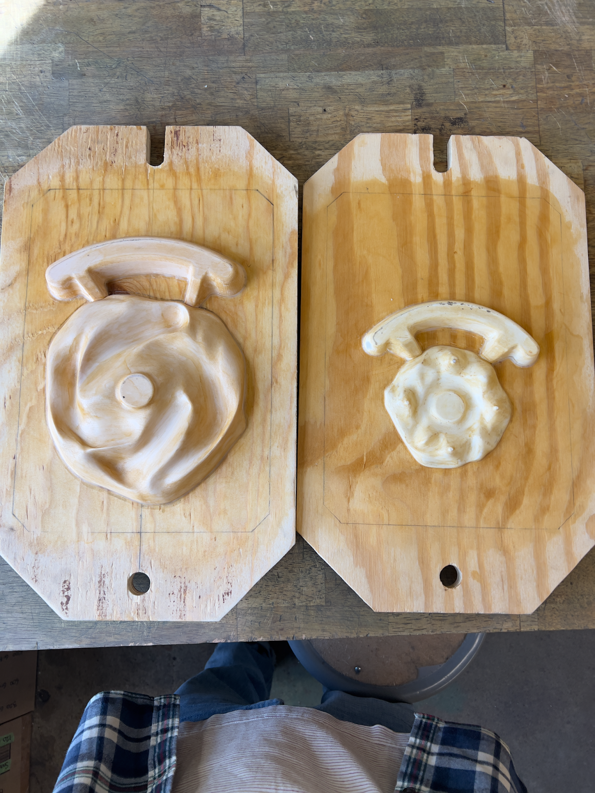
My two fixed patterns: 3D printed in PLA, fixed onto pattern boards.
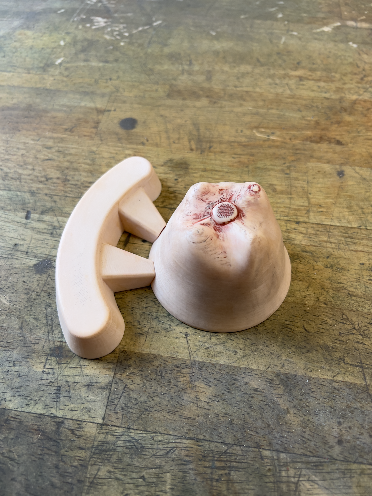
Loose pattern: 3D printed using PLA.
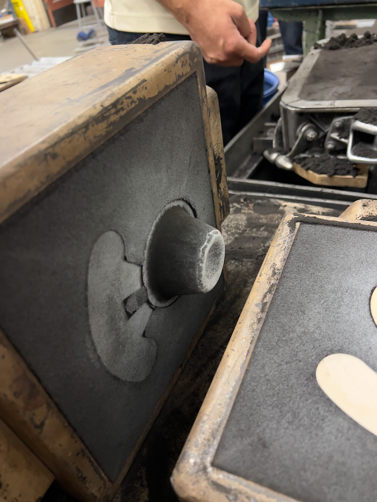
The ramming up process for the top cup.
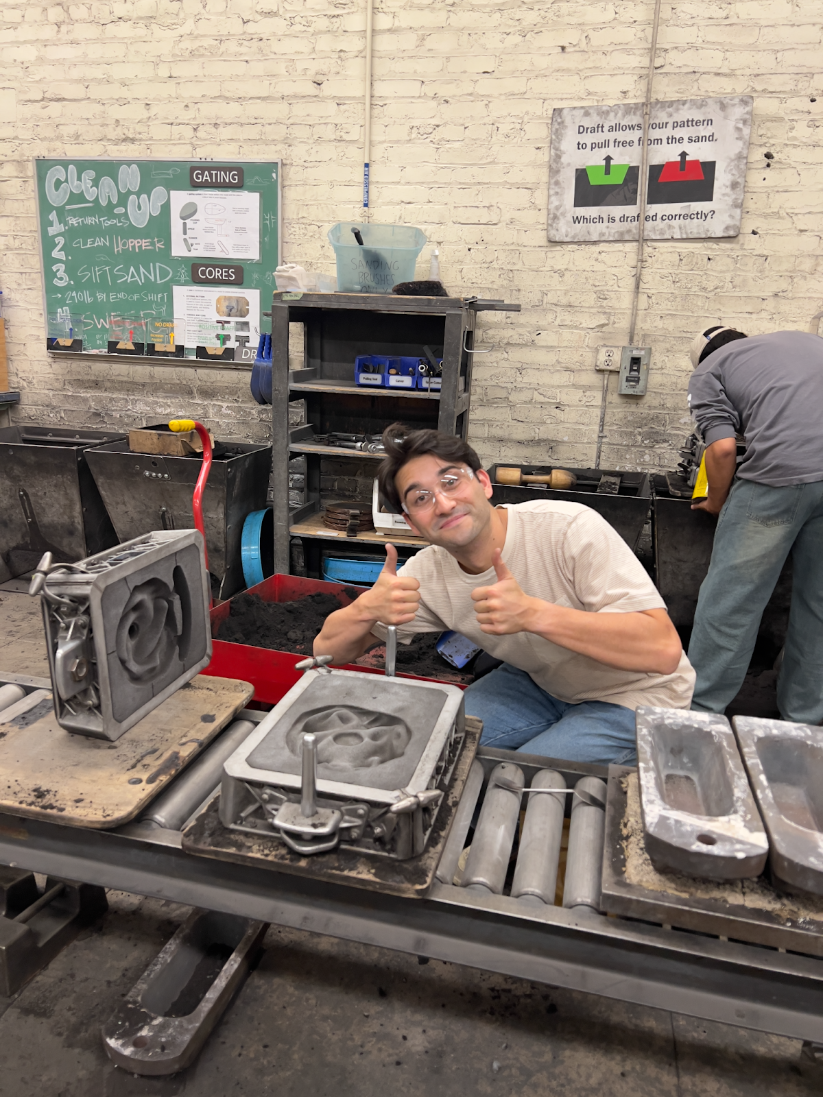
Successful ram up!
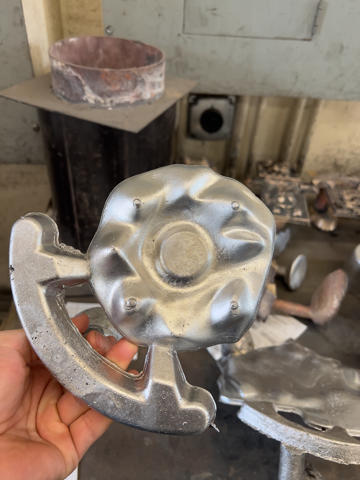
Resulting part after pouring aluminum 356A.
Post Processing
On the mill, I fixtured each part using strap clamps and a piece of sacrificial material as needed. I then drilled each hole with the appropriate sized drill bit, and bored holes using an end mill.
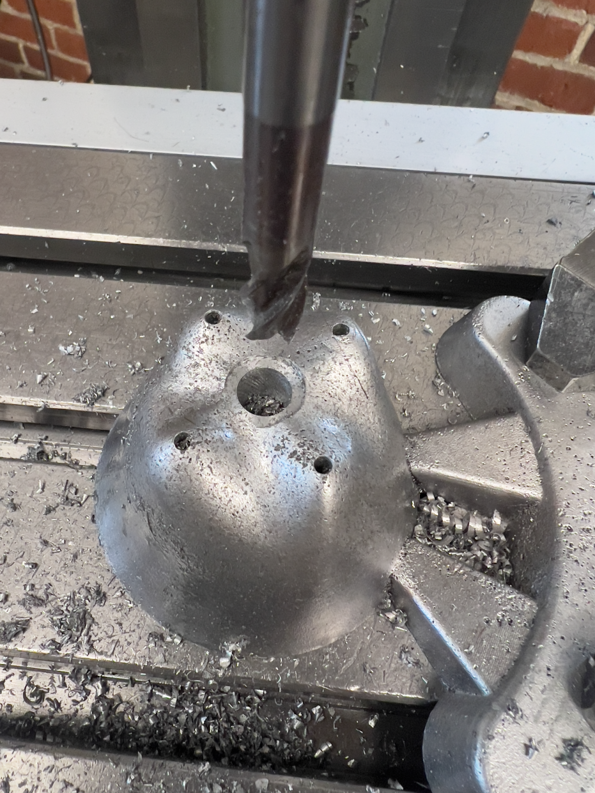
Boring the center of the top cup for mounting.
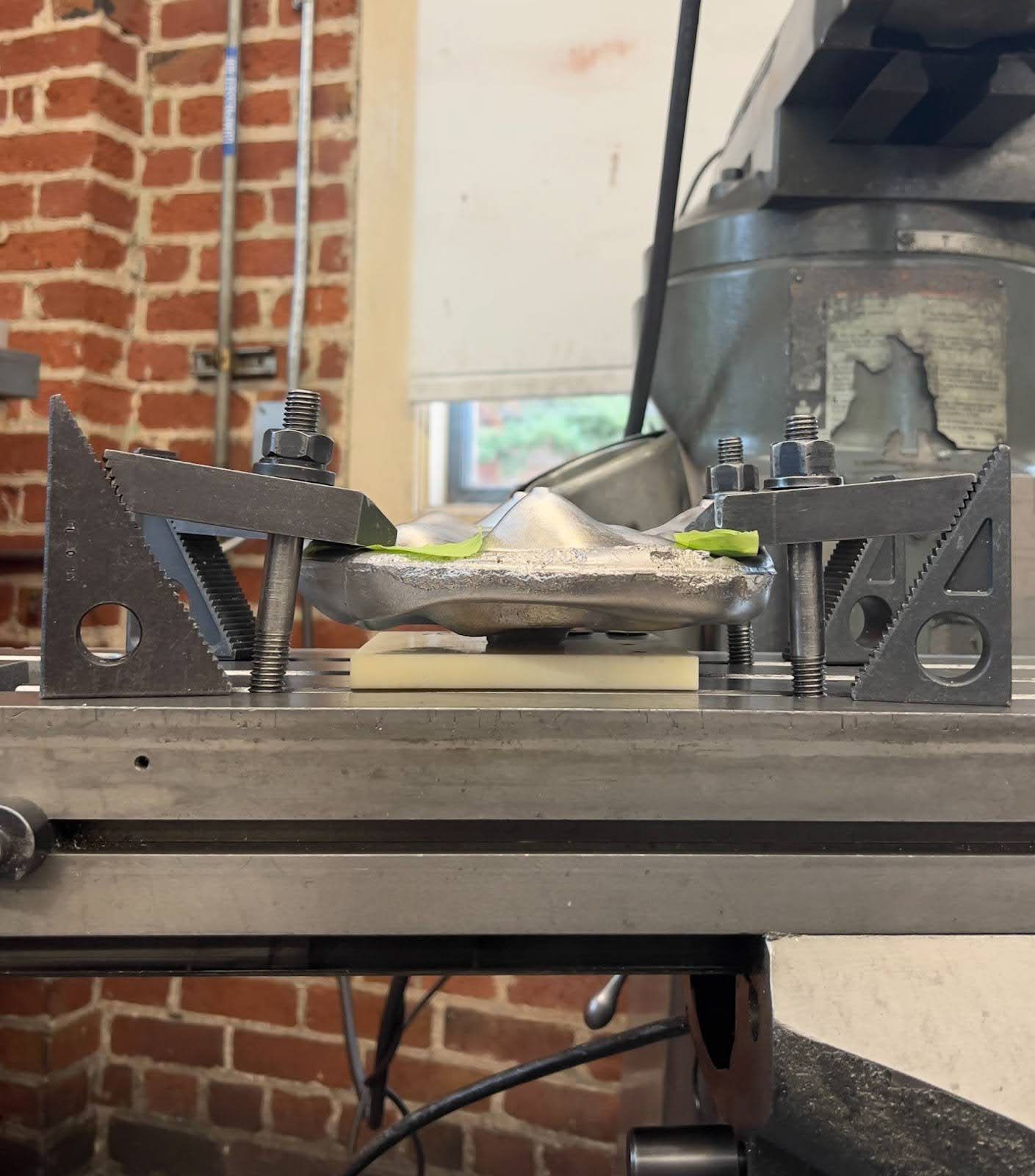
Fixturing one of the organic shapes onto the mill with strap clamps and sacrificial material underneath.
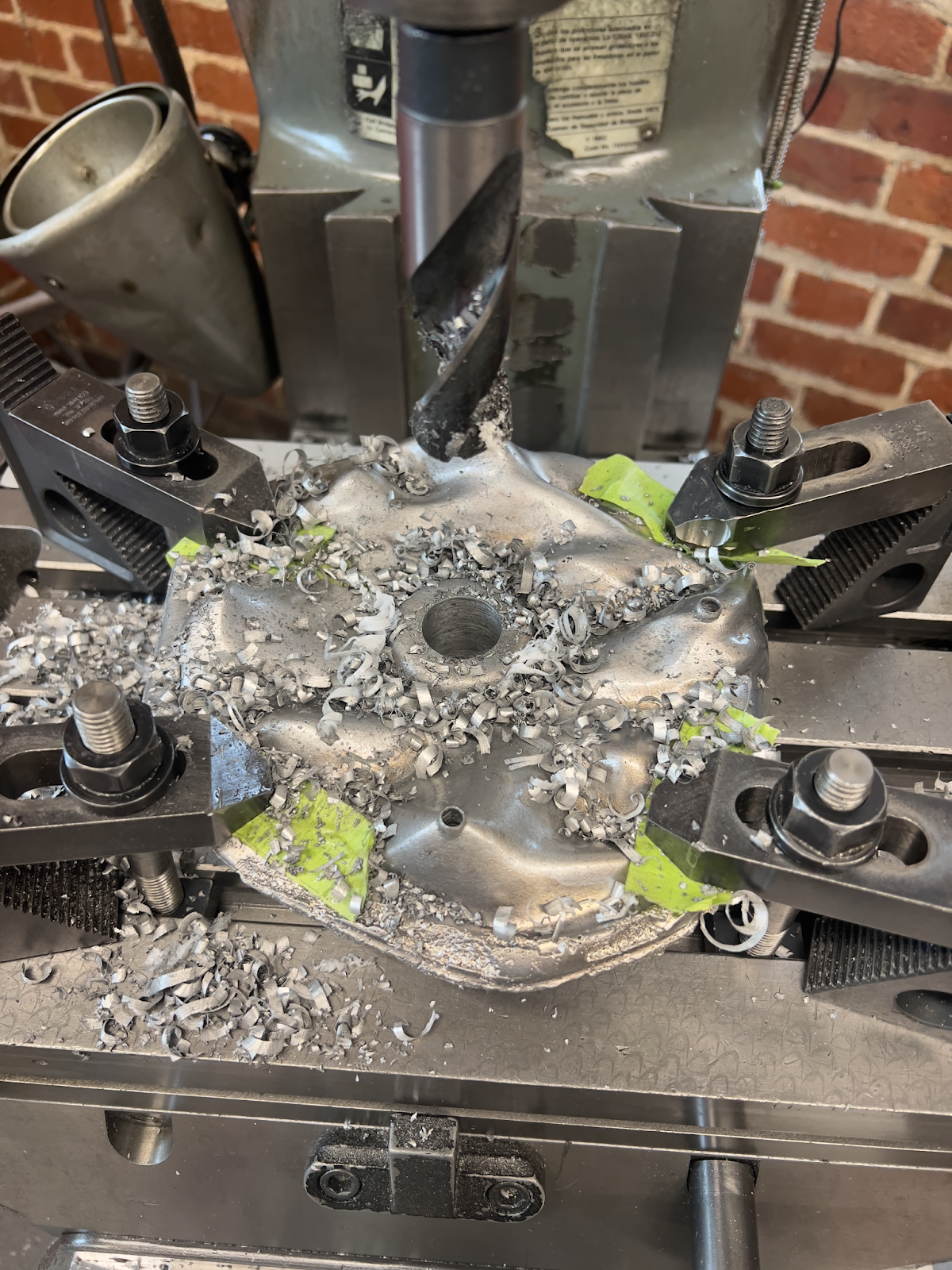
Drilling the mounting hole.
Wooden Base
Because redwood is toxic and isn't allowed in my school's wood shop, I used cherry since its color and grain is close to that of redwood. I started with a 12" x 12" x 3/4" board and used a laser-cut template to plunge route the features for each wine glass. Next, I drilled holes for mounting the center rod and sanded to 320 grit. To finish, I applied three coats of danish oil to bring out the color, and three coats of polyurethane to protect from wine droplets.
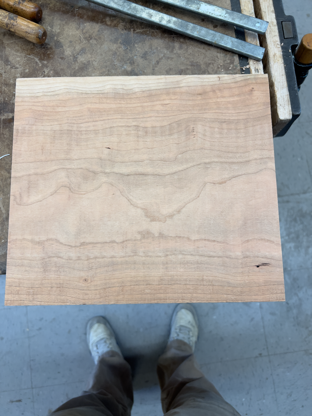
Started with a cherry board, 12" x 12" x 3/4""
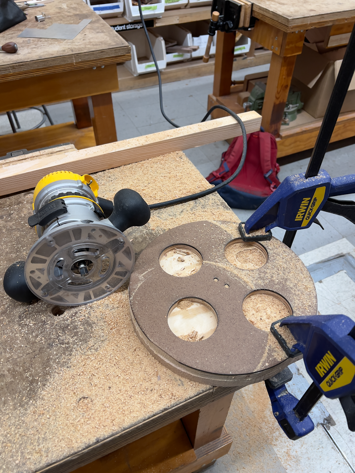
Using a laser cut template.
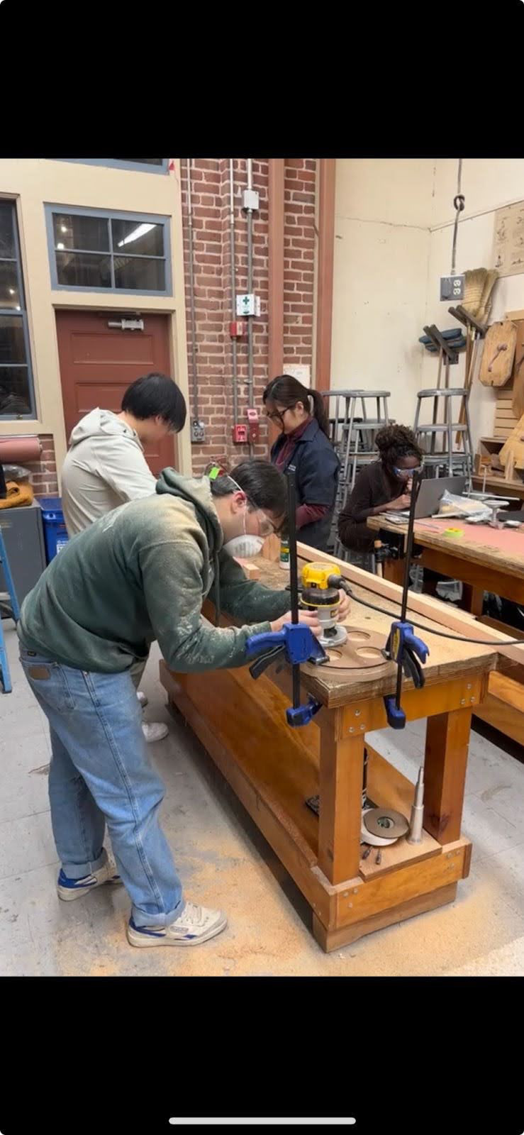
Plunge routing the glass holders.
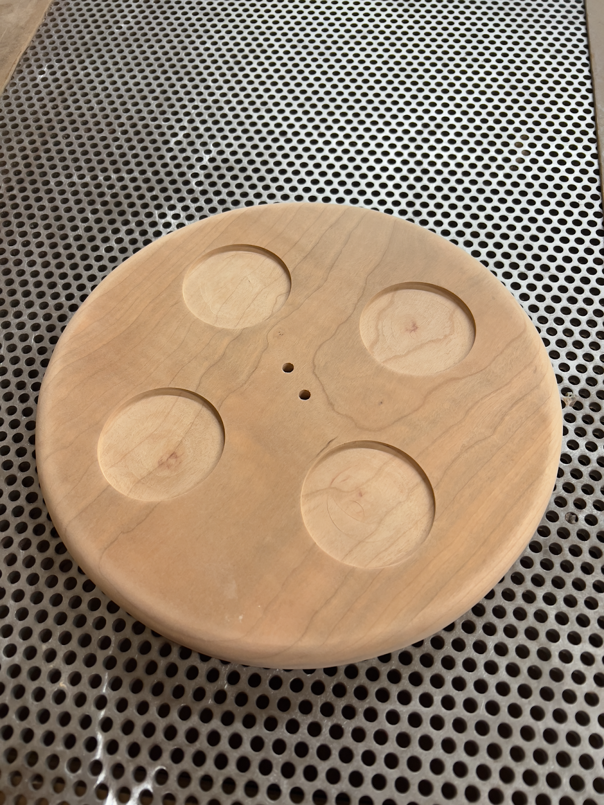
Wooden base after sanding to 320 grit.
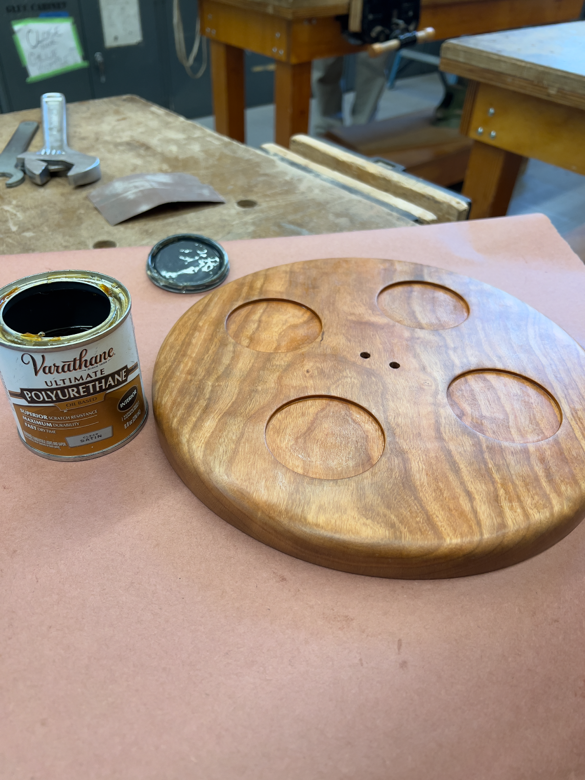
I finished the wooden base using three coats of danish oil, followed by three coats of polyurethane.
Finishing
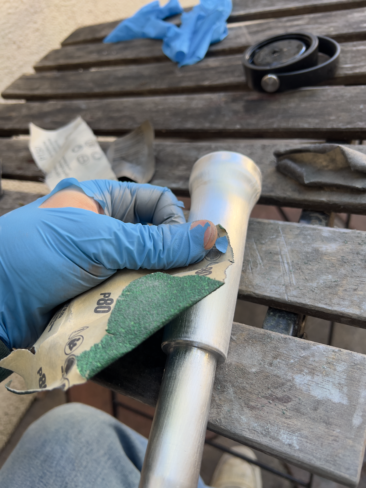
Center Rod
I first sanded the rod to 2000 grit sandpaper and polished it. To emulate redwood tree bark, I went back over it with 150 grit sandpaper, creating a brushed finish.
Sanding out the machining lines.
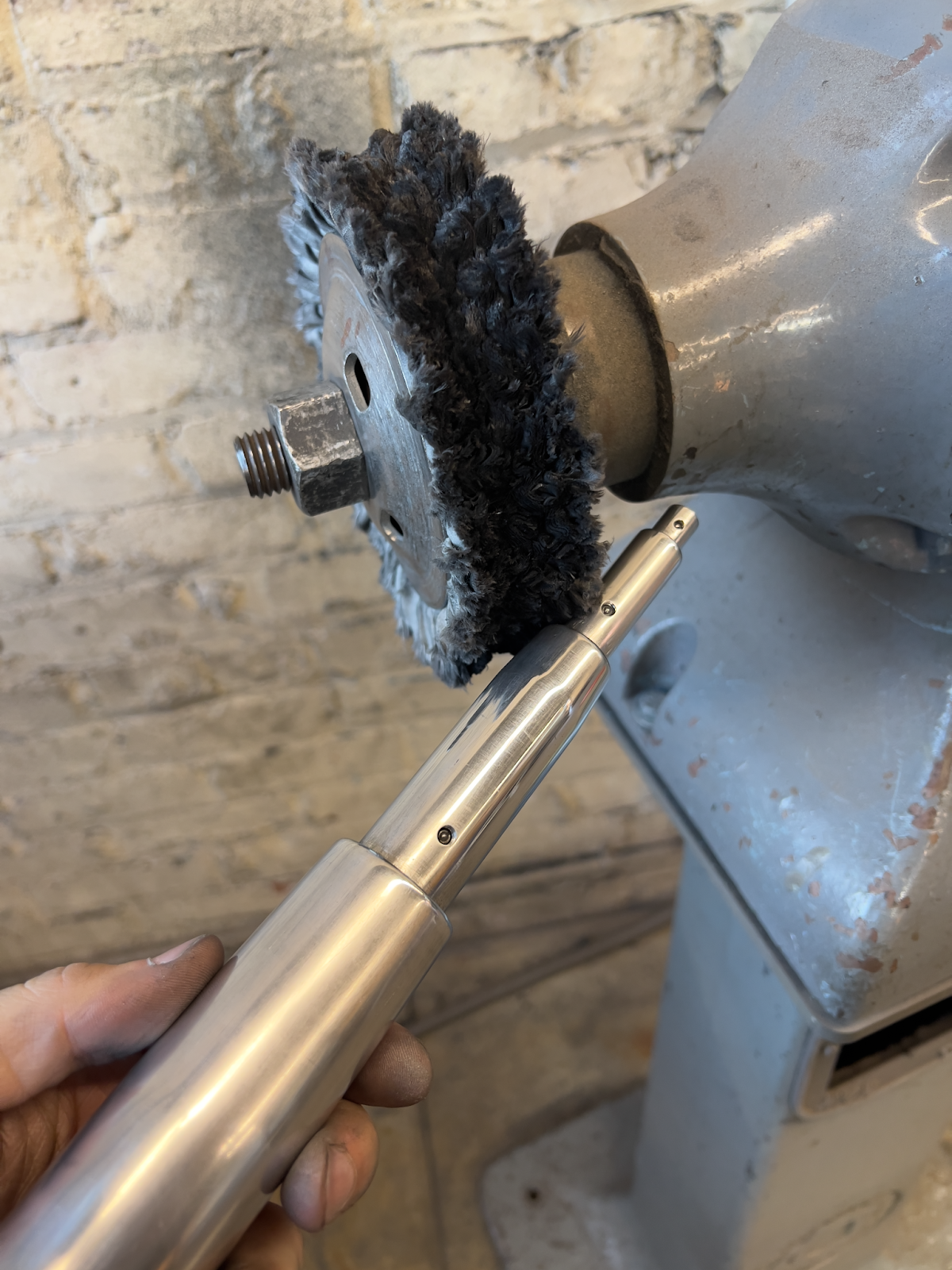
Polishing the center rod.
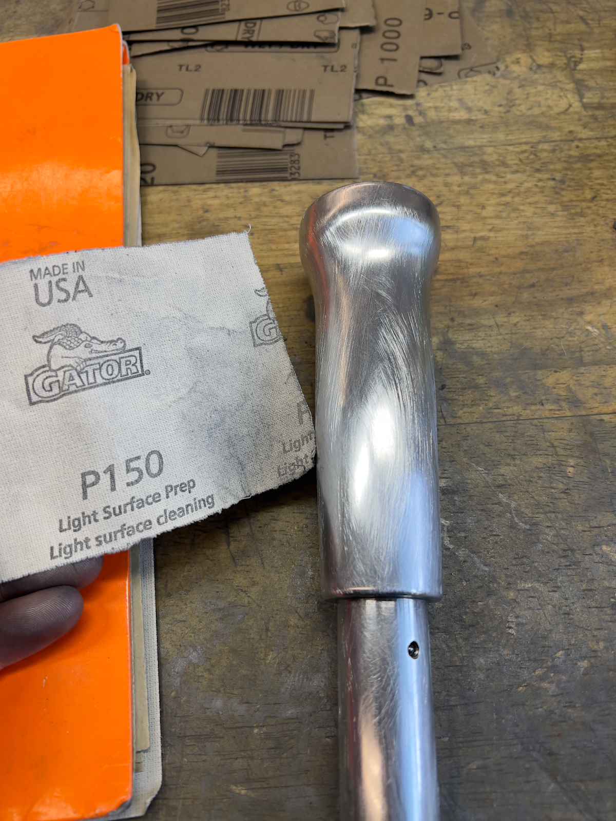
Emulating redwood tree bark by creating a brushed aluminum finish with 150 grit sandpaper.
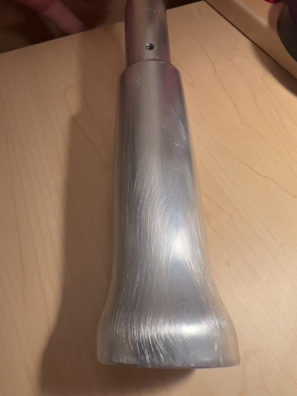
Finished component!
Cast Parts
After removing the gates and runners, I sanded out the parting lines with 80 grit sandpaper. Then, I sanded and polished all the parts that would touch liquid: the inside of the top cup and the channels. To add contrast, I left everything else with a natural, cast finish.
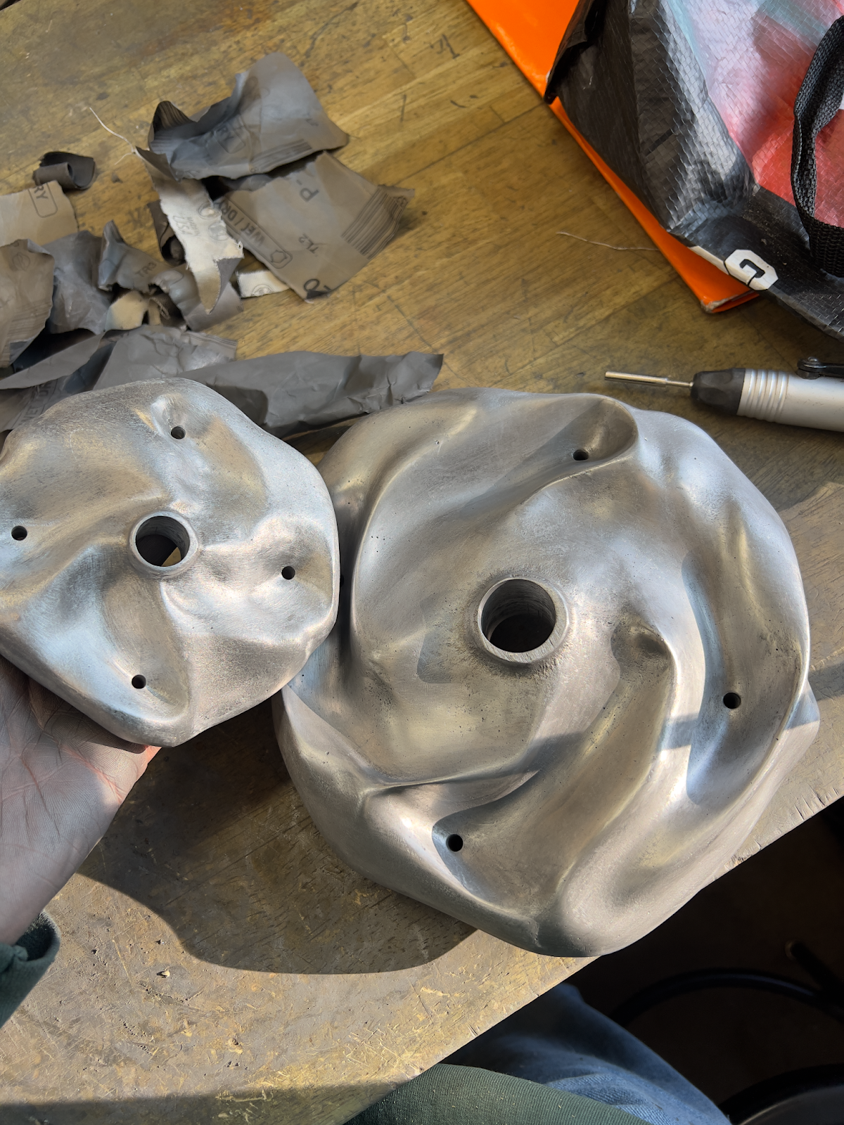
The two plates after initial sanding.
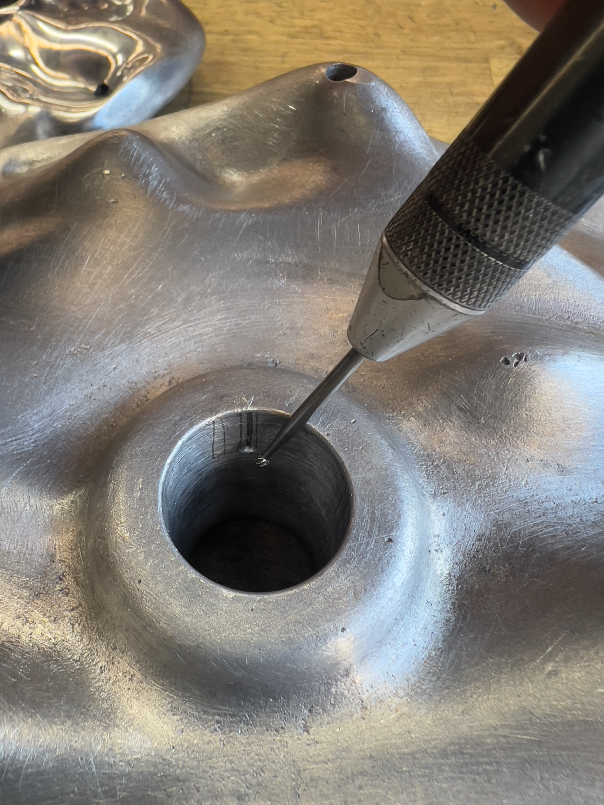
Sanding out the center mounting hole.
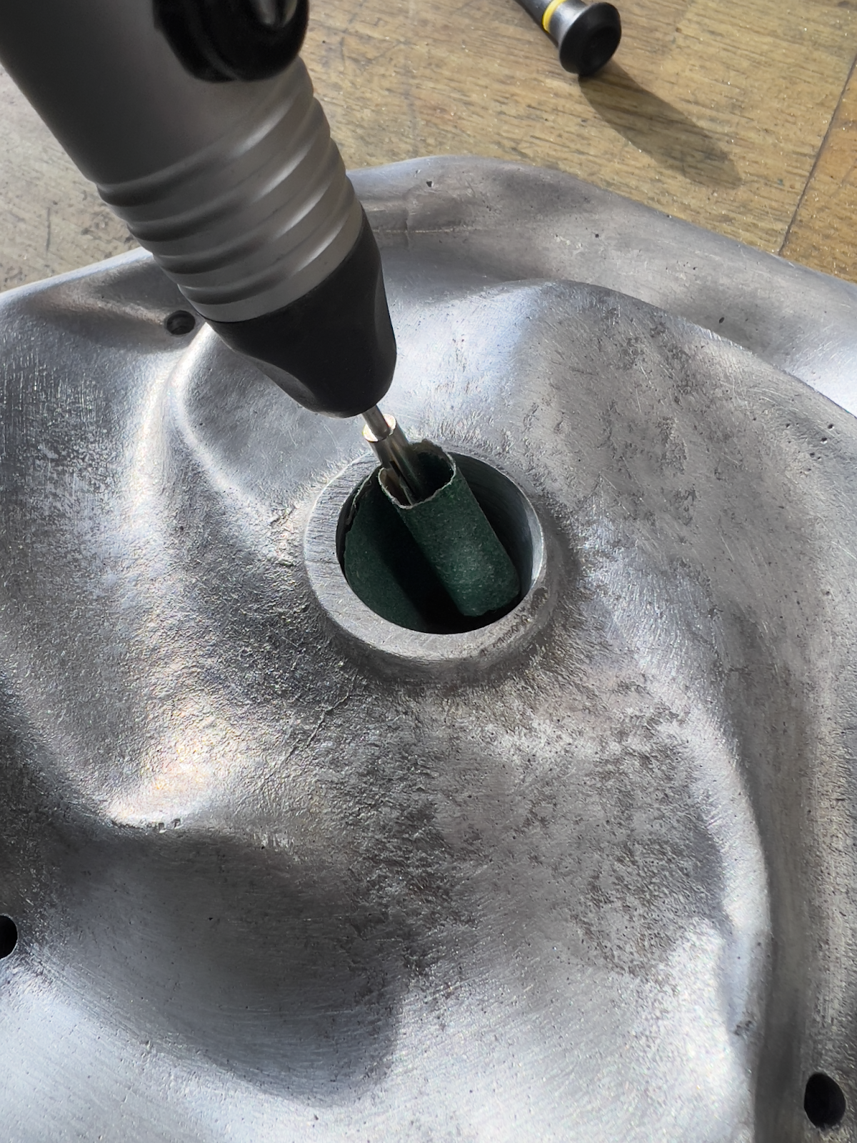
Using a dremel to add the detent for the ball detent.
Top plate after sanding to 2000 grit and polishing.
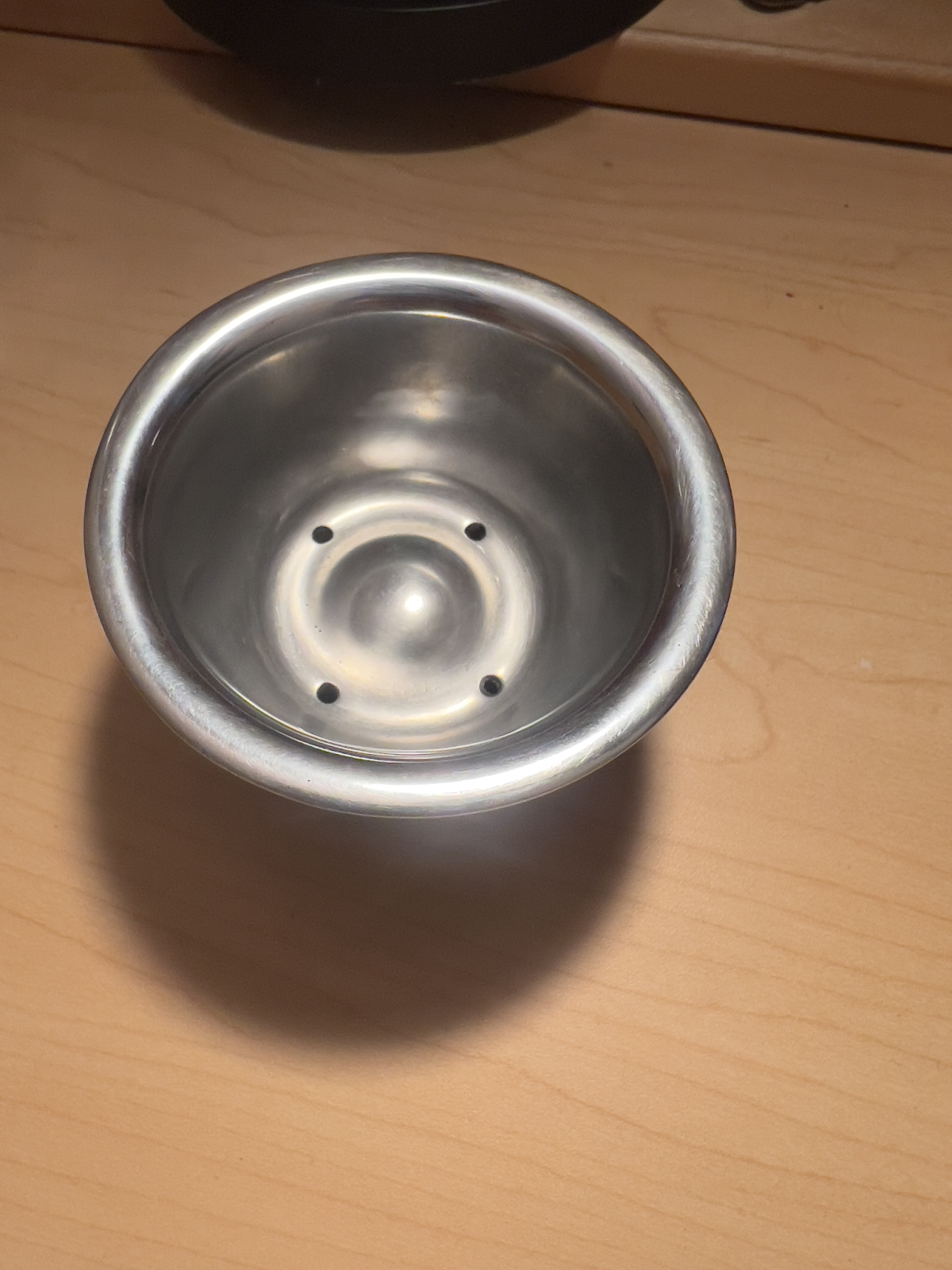
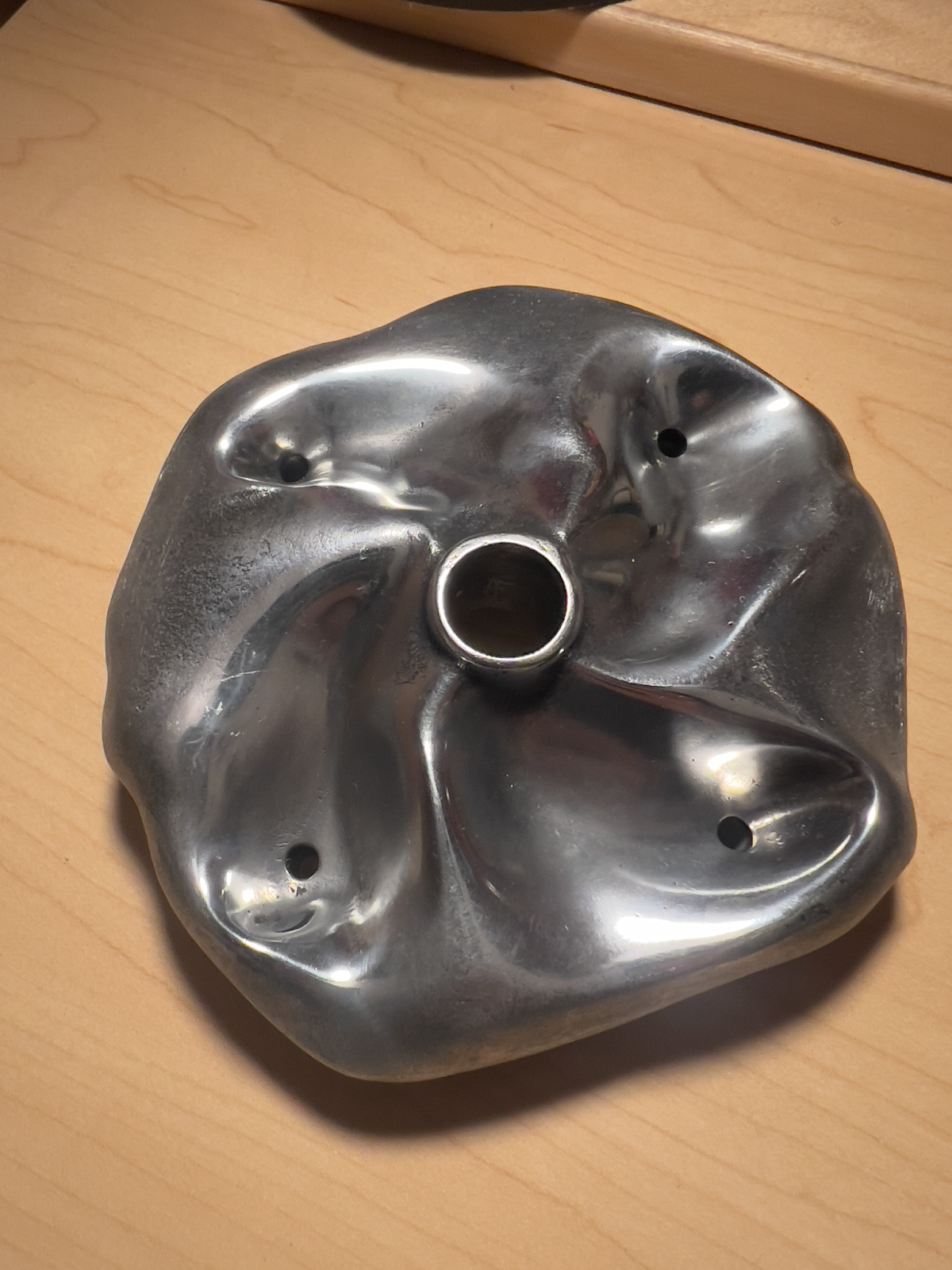
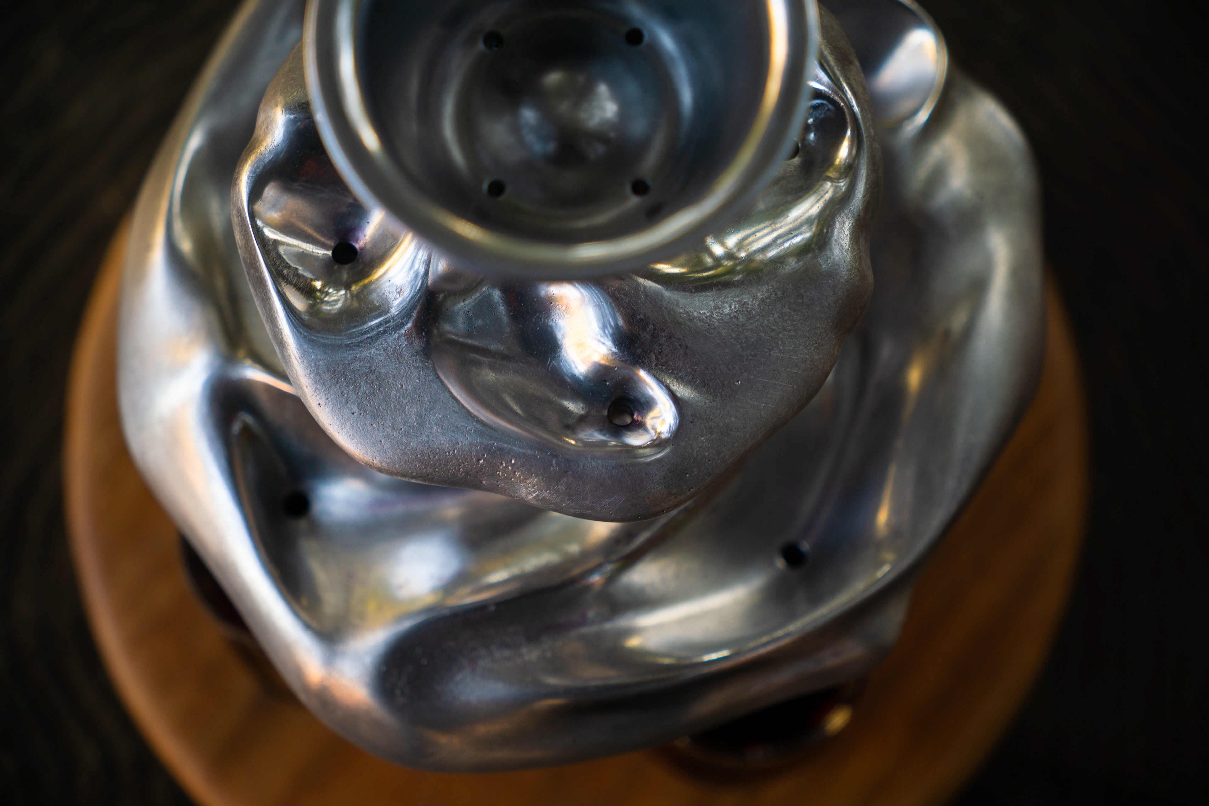
Finished top cup after sanding to 2000 grit and polishing.
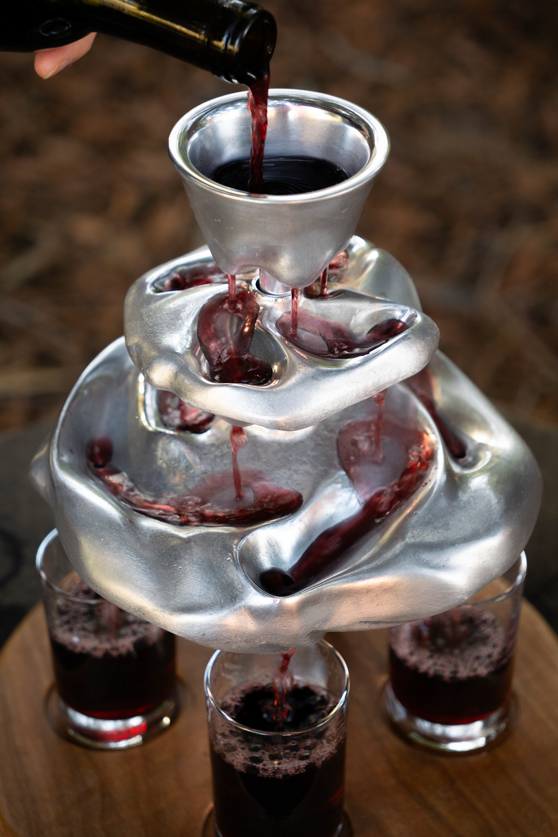
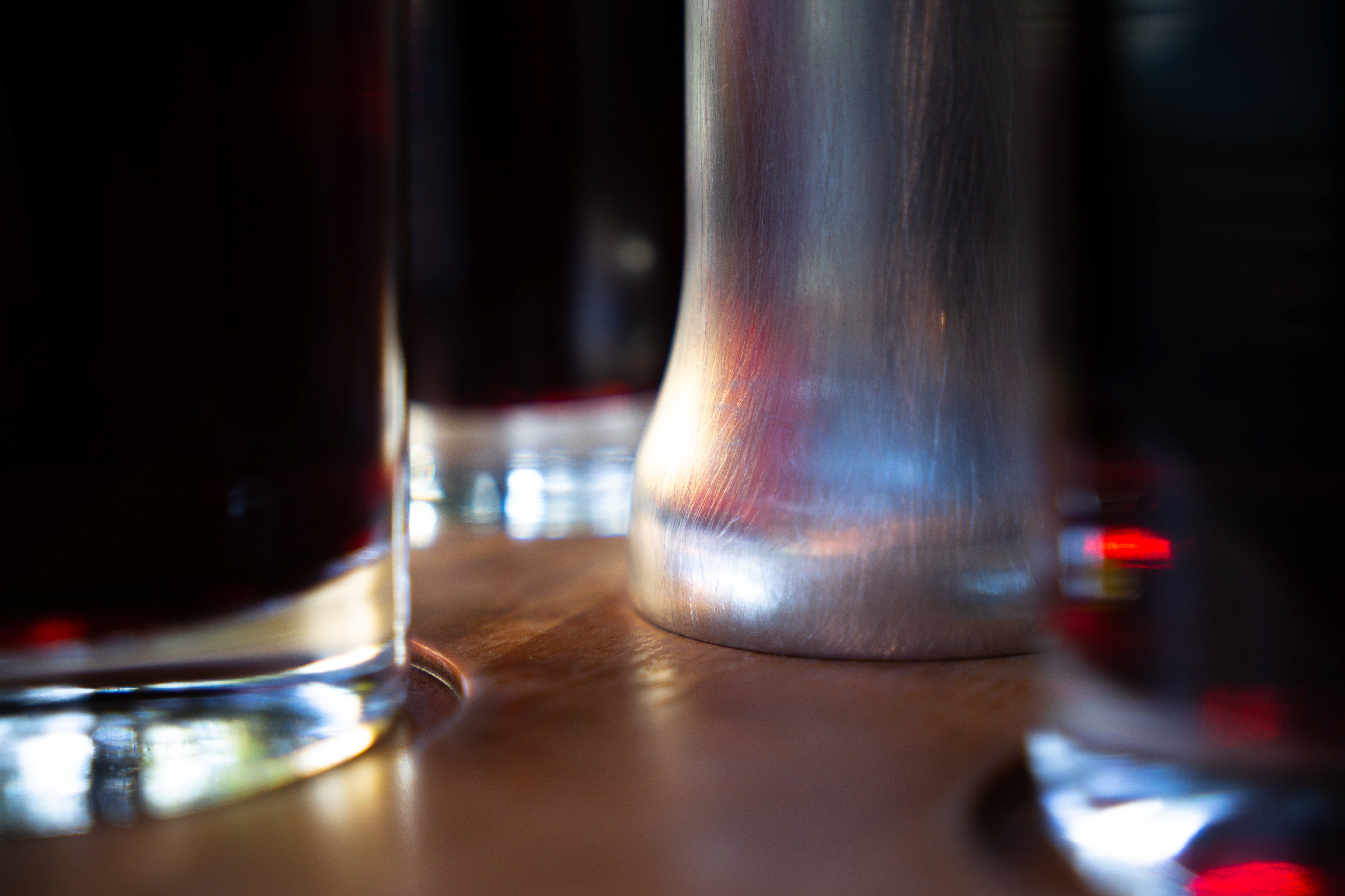
Final Product
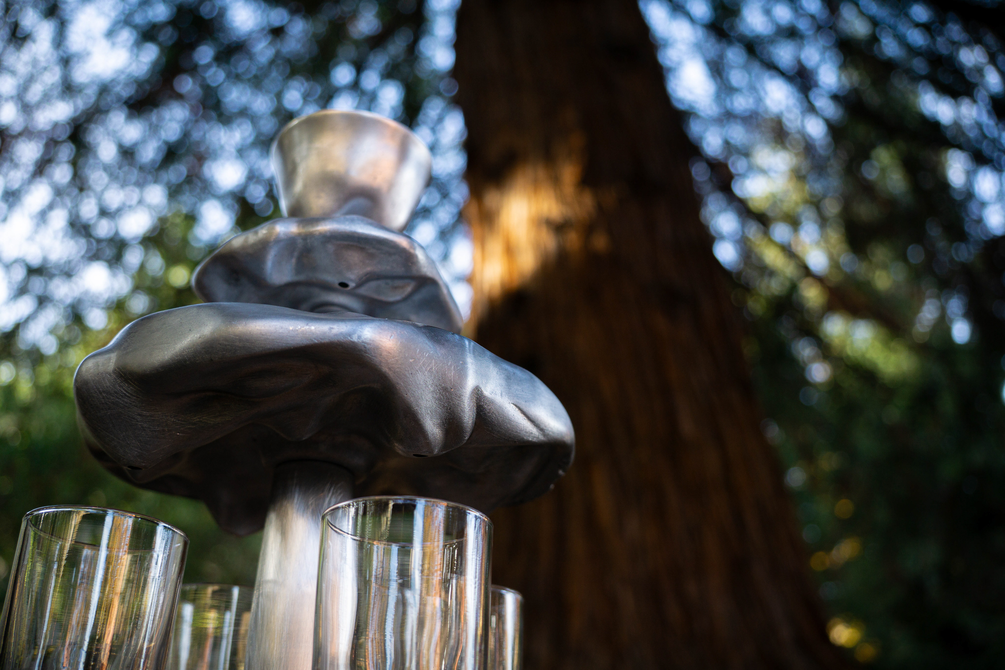
Reflection
This was an extremely meaningful project for me, as I was able to incorporate two different parts of my childhood into one. Also, this was my first time sand casting and using a lathe and a mill. I had a blast.
What I learned:
1. Design for manufacturing. I had sized the center rod to arbitrary diameters instead of sizing them to the drill bits I would be using, causing me to have larger gaps than I expected.
2. Decide on the finish before touching anything. I had initially planned to sand blast the parts that weren't polished. I sand blasted the outside of the cup, only to realized I didn't like how it looked, so I re-sanded it. To avoid this, I should have tested the finish on a scrap part to make sure I was confident about the choice.
Going forward, I hope to be able to use this experience to be more intentional about my dimensions, tolerances, and finishes.